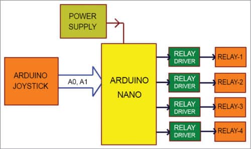
 This project can be used to control up to four industrial electrical appliances with the help of a joystick and an Arduino Nano board. The block diagram of the joystick-controlled industrial automation system is shown in Fig. 1.
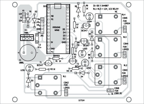
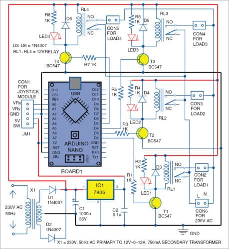
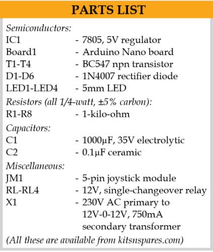
The circuit diagram of the joystick-controlled industrial automation system is shown in Fig. 2. It is built around Arduino Nano (Board1), 5V regulator 7805 (IC1), four npn transistors (T1 through T4), joystick module (JM1), transformer (X1), four 12V single-changeover relays (RL1 through RL4) and a few other components.
Joystick module
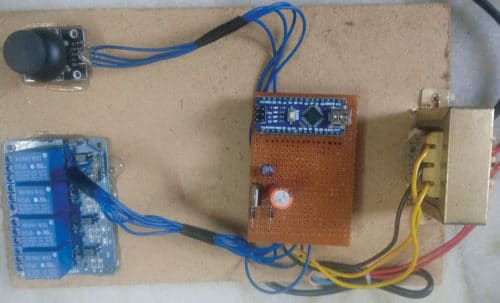
Joysticks are available in different shapes and sizes. A typical joystick module is shown in Fig. 3. This joystick module provides analogue voltage outputs. Output voltage changes according to direction of the shaft. You can get direction of shaft movement by interpreting voltage changes using a microcontroller (MCU).
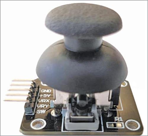
This joystick module has two axes: x and y. Each axis is controlled by shaft of the potentiometer mounted on of the joystick module. Potentiometer outputs VRx and VRy at connector CON1 are variable points. VRx and VRy act as the voltage divider.
When joystick shaft is in normal position, it is in standby mode. When it is moved along horizontal axis (right and left), voltage at VRx pin changes. Similarly, when it is moved along vertical axis (up and down), voltage at VRy pin changes. So, we have four different output signals for four directions of the joystick, which are connected to two analogue-to-digital converter (ADC) input pins A0 and A1 of Arduino Nano.

When the shaft is moved, voltage on each pin goes high or low depending on direction. The joystick module also comes with one push-button switch for interruption purpose (this function is not used here). The joystick module is interfaced with Arduino Nano, which comes with an inbuilt ADC, as shown in Fig. 2.
Arduino Nano drives four relays (RL1 through RL4) through its pins D2, D3, D4 and D5.
Power supply
Regulated power supply is designed with a full-wave rectifier circuit. It consists of D1 and D2 (1N4007) rectifier diodes, capacitors C1 and C2, IC1 7805 and 230V AC primary to 12V-0-12V, 750mA stepdown transformer (X1). In this project, mainly two voltages are required: 12V and 5V. 12V DC is used for relays, and 5V for Arduino Nano MCU.

Arduino Nano
It is a small board compatible with ATMega328 MCU. It has the following features:
- Operating voltage (logic level): 5V
- Input voltage (recommended): 7V-12V
- Input voltage (limits): 6V-20V
- Fourteen digital I/O pins (of which six provide PWM output)
- Eight analogue input pins
- DC current per I/O pin: 40mA
- Flash memory: 32kB (ATmega 328), of which 2kB is used by bootloader
- SRAM: 2kB (ATmega328)
- EEPROM: 1kB
- Clock speed: 16MHz
Operation
When the joystick module is in ideal state, digital value for both VRx and VRy is 512. ADC of Arduino is ten-bit, and digital value varies from 0 to 1023 levels according to analogue voltage received from the joystick. Ideally, the joystick is in midpoint or standby mode, so value shows is 512.
Case 1
When you move the shaft in x-left direction, digital value is less than 50. In this condition, pin D2 of Board1 is made high from the program, BC547 transistor T1 conducts, relay RL1 is energised and load connected across RL1 turns on. Diode D3 is used as freewheeling diode to eliminate back EMF.
Case 2
When you move the shaft in x-right direction, digital value is greater than 900. In this condition, pin D3 of Board1 is made high, BC547 transistor T2 conducts, relay RL2 is energised and electrical load/device connected across RL2 turns on.
Case 3
When you move the shaft in y-down direction, digital value is less than 50. Here, pin D4 is made high, BC547 transistor T3 conducts, relay RL3 is energised and load connected across RL3 turns on.
Case 4
When you move the shaft in y-up direction, digital value is greater than 900. Here, pin D5 of Board1 is made high, BC547 transistor T4 conducts, relay RL4 is energised and load connected across RL4 turns on.
Software program
Main operation is done by the software program loaded into the internal memory of Arduino Nano. The program is written in Arduino programming language or sketch. Arduino IDE 1.6.8 is used to compile and upload the program.
ATmega328P on Arduino Nano board comes with a pre-programmed bootloader that allows you to upload a new code to it without using an external hardware programmer.
Connect Arduino Nano board to the PC and select the correct COM port in Arduino IDE. Compile the program/sketch (joystick_control.ino) and select the correct board from Tools->Board menu in Arduino IDE. Upload the sketch to load the program to the internal memory of the MCU. The sketch is at the heart of the system and carries out all major functions. In this project, external header files are not required for programming. It is a simple way to detect joystick values, and compare VRx and VRy values using if-else ladder functions to control four appliances.
Download Source Folder: click here
Construction and testing
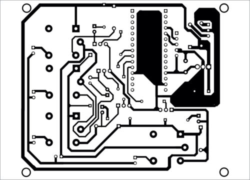
An actual-size PCB layout of the joystick-controlled industrial automation system is shown in Fig. 4 and its components layout in Fig. 5. Connect the power supply from the transformer to the PCB at X1. Connect joystick output wires to the PCB at JM1. After loading the program into Arduino Nano, as described earlier, mount it on the PCB on the space provided for it. Switch on the power supply. Now you can move the shaft left, right, up and down to control the electrical appliances. The author’s prototype is shown in Fig. 6.