
 This circuit monitors light in surrounding areas at all times, displays light level on the LCD and sounds an alarm when light level becomes low. Such systems are being developed and used in such applications as healthcare, defence, mining, robotics and so on.
In the underground mining environment and caves, light is normally low, and it becomes difficult to work under low-light conditions for people having low vision. Hence, light level needs to be checked in these areas in advance using this kind of a circuit, or a similar device with camera.
This circuit is a low-cost system that can be installed on a drone to check the intensity of light at various remote locations in underground mines and caves. It can also be used as an energy saver, duty schedule indicator and home automation system.
Circuit and working
The circuit diagram of the light-level monitoring system for mining and archaeology is shown in Fig. 1. It is built around Arduino Uno Board1, piezo buzzer PZ1, LDR1, 16×2 LCD (LCD1) and a few other components.
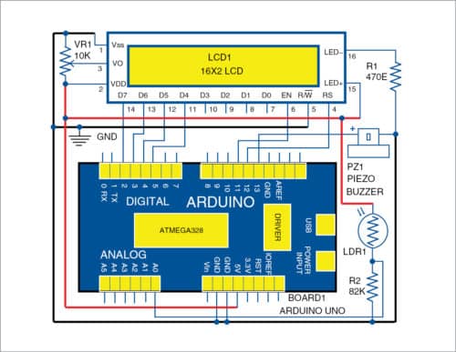
When light falls on the surface of LDR1, resistance of LDR1 is low and, hence, high current flows through it. At night or in darkness around LDR1, resistance increases and goes up to mega-ohms and, so only small current flows through LDR1. Then, the piezo buzzer sounds an alarm indicating the low level of light.

Level of light is displayed on LCD1 with percentage of light intensity level and vision status, such as no vision, dim vision, clear vision and crystal clear. Voltage output across LDR1 is analogue, and it gets converted to digital through an inbuilt analogue-to-digital converter in Arduino. Analogue voltage ranges from 0V to 5V, and equivalent digital range from 0V to 1023V is displayed on the serial monitor of Arduino IDE.
Light sensor
A photo resistor or photo-conductive cell is a light-dependent variable resistor. Its resistance decreases with increase in light intensity falling on it. LDR1 exhibits photoconductivity property. A photo resistor can be used in many circuits to detect light intensity and appliance switching operations.
Buzzer
A piezoelectric buzzer (PZ1) produces sound based on piezoelectric effect. Generation of pressure variation or strain by the application of electric potential across a piezoelectric material is the underlying principle here.

A piezoelectric buzzer consists of piezo crystals between two conductors. When a potential is applied across these crystals, they push on one conductor and pull on the other. This push and pull action results in a sound wave.
Display
LCD1 module has sixteen pins. Pin 1 is ground and pin 2 is Vcc. Pin 3 is used for contrast adjustment. This is done by connecting potmeter VR1. Pin 4 is register select (RS) pin, and pin 5 is for read/write mode. Logic high at this pin activates read mode and logic low activates write mode.
Pin 6 (EN) is meant for enabling LCD1. A high-to-low signal at this pin enables the module. Pin 7 (D0) through pin 14 (D7) are data pins. Commands and data are fed to LCD1 module through these pins. Pin 15 (LED+) is anode and pin 16 (LED-) is cathode of the inbuilt backlight LED.
Software
The program is written in Arduino programming language/sketch. A0 through A5 on Arduino Uno are analogue input signals. The program detects input signals on these pins and prints the corresponding voltage levels on the serial monitor in PC and on LCD1. LDR1 is connected to A0 pin and piezo buzzer to pin 13 of Arduino Uno.
Arduino IDE is used to compile and upload the program to Arduino. Select the correct board from BoardTools menu in Arduino IDE, select COM port and upload the program (vision.ino) through the standard USB port in the computer.
Download Source Folder
Construction and testing
A PCB layout of the light-level monitoring system is shown in Fig. 2 and its components layout in Fig. 3. After assembling the circuit, place the circuit at a location such that light falls on LDR1.

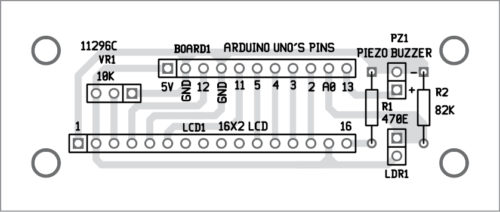
Download PCB and Component Layout PDFs: click here
Check connections as per the circuit diagram. Check the light intensity level on LCD1. Whenever there is low light intensity, that is, below twenty per cent, piezo buzzer will sound, and LCD1 will update the status to no vision or dim vision, depending on the light around LDR1 sensor.
If light intensity is above twenty per cent, piezo buzzer will not sound, and LCD1 will show the status as clear vision or crystal clear, depending on the light around LDR1 sensor.
Navpreet Singh Tung is assistant professor in department of electrical engineering, Bhutta Group of College, Punjab


