
 Light-dependent switches are used in automatic hand-dryers and flushers in toilets. Here is a simple light operated switch that works in normal light also. You can affix it on the main door of your house to work as an automatic doorbell or a thief alarm. The bell rings as soon as someone’s shadow falls on the sensor of this device.
Light operated switch circuit
The sensor is a light-dependent resistor (LDR) made of CdS semiconductor whose resistance changes with light. In the presence of light its resistance becomes low, while in darkness the resistance goes high.
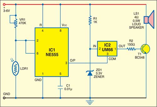
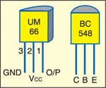
The circuit uses timer IC 555 and melody-generator IC UM66. The maximum working voltage of UM66 is 3.3V. A Zener diode is used to provide the maximum required voltage. Melody IC UM66 gets the input from timer NE555 and its output is fed to the base of transistor T1 through resistor R2. A 470-kilo-ohm preset (VR1) is used to change the threshold operation of the circuit.
Circuit operation
When light falls on LDR1, its resistance decreases and the potential difference between pin 2 of IC1 and the ground decreases. In this condition, the output of the timer remains high. This high voltage at the ground terminal of UM66 stops its operation, so you will not hear any melody.
When someone’s shadow falls on the LDR sensor, its resistance increases and the potential difference between pin 2 of IC1 and ground increases. The output of the timer goes low. This low voltage at ground terminal of UM66 starts its operation. The pulse generated by UM66 is amplified by transistor T1 and fed to speaker LS1. Thus when light stops falling on the LDR, you will hear a melodious tone.

Construction & testing
The circuit works off 3-6V DC, which can be produced by 1.5V pencil cells. Assemble it on a general-purpose PCB and enclose in a suitable cabinet. Avoid dry-soldering on the PCB for better working of the circuit.
You can install the unit on the door in front of a normal bulb such that light falls directly on the LDR and as soon as someone comes in front of the door, he obstructs light falling on the LDR and the bell rings.
To make the circuit work other way round, i.e., the bell sounds when light falls on the LDR and is silent when someone’s shadow falls on it, disconnect resistor R1 from the power supply rail and connect it to pin 3 of IC1. Thereafter, disconnect ground pin 3 of UM66 from pin 3 of IC1 and connect to ground rail.

This article is a part of the Top 10 LDR-based Electronics Projects. If you want to read more projects based on LDRs can go through this article.
The article was first published in February 2007 and has recently been updated.


