
 Protect your valuables from burglary using this simple locker guard circuit. It generates warning beeps when someone attempts to open the locked safe. The warning alarm sounds at an interval of a few seconds, so it is not annoying. Even after closing the door, the alarm will continue sounding for a few seconds.
Locker guard circuit
The circuit uses a light-dependent resistor (LDR) to detect the ambient light when the door of the locker is opened. When light falls on LDR1, it conducts and capacitor C1 charges. When the voltage across capacitor C1 increases to about 4.7 volts, zener diode ZD1 conducts to provide base current to transistor T1. Resistor R1 reduces the sensitivity of LDR1 to provide the time delay to charge capacitor C1. Resistor R2 provides the discharge path for capacitor C1 and resistor R3 keeps the base of transistor T1 at the ground potential when the zener diode stops conducting.
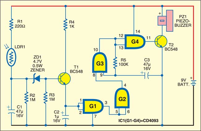
When door of the locker is opened, transistor T1 conducts and input pins 1 and 2 of gate G1 become high. The low output from gate G1 is fed to gate G2, whose output goes high to activate the oscillator built around gates G3 and G4. The output from gate G4 is used to bias transistor T2 and the buzzer connected to its collector sounds when it conducts. Capacitor C3 and resistor R5 determine the frequency of oscillation.
When door of the locker is closed, transistor T1 does not conduct and as a result, the output of gate G2 remains low. This deactivates the oscillator built around gates G3 and G4. The low output of gate G4 makes transistor T2 non-conducting and the buzzer remains silent.
Construction & testing
Assemble the circuit on a common PCB as compact as possible and enclose in a small plastic case with holes for LDR1 and buzzer PZ1. LDR1 should be oriented such that light directly falls on it when the door of the locker is opened. In other words, when the door is closed, light should not fall on LDR1.

Delay time can be increased or decreased by changing the value of C1. In the standby mode, current consumption is very low, so a 9V battery is sufficient to power the circuit for long periods.
The article was first published in January 2007 and has recently been updated.


Can Ic 7400 used instead of Ic4093