Dual buffer with differential inputs
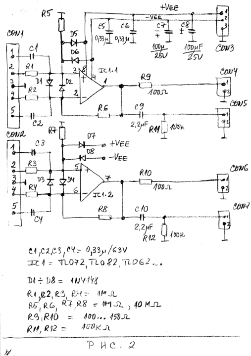
Sometimes we should capture and observe with oscilloscope differential signals. Most of the oscilloscopes need special differential probes or pre-amplifiers in order to capture these signals. Figure 2 presents the schematic diagram of the buffer with differential inputs.
The buffer is with two channels.

We can use dual operational amplifiers as TL072, TL082, TL062 or similar. The buffer is with input resistance above 1MOhm. The input resistance depends mainly on resistors R1, R2, R3 and R4. If we have R1 = R2 = R3 = R4 = 1MOhm the voltage gain is +1. If we have R1 = R2 = 1MOhm and R3 = R4=10MOhm the voltage gain is +10.
Preferably, the output of the buffers from Figure 1 and Figure 2 should be loaded with resistance higher than 10 kOhm.
The power supply
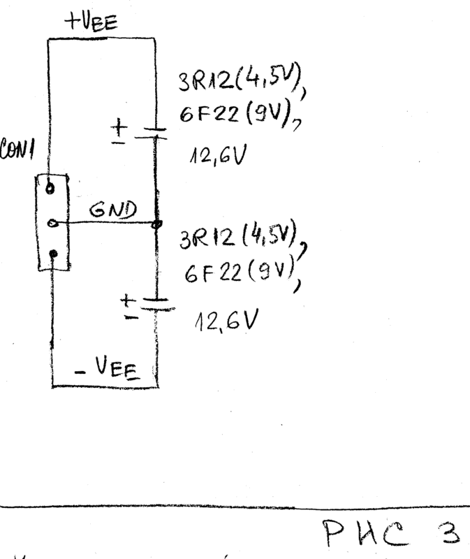
The buffers may be used in the full power supply range of the amplifiers. In most of the cases we can use +-9V from small batteries 6F22 or +-12.6V from two rechargeable batteries of 12V. Figure 3 shows how we can use dry batteries or rechargeable batteries to provide power supply for the buffers.

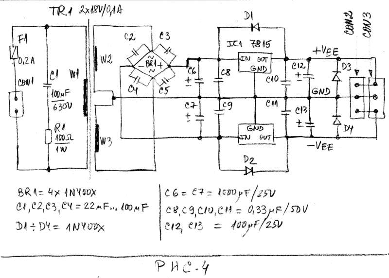
The preferred power supply should be well filtered power supply of +-15V. Figure 4 shows the circuit diagram of power supply whish can provide +-15V for the buffers.

We can use the voltage regulators 78L15+79L15 (0.1A), 78M15+79M15 (0.4A), 7815+7915 (1A) and similar.


