
 The circuit presented here can measure voltage (V), current (A) and wattage (W) on an OLED. It is actually voltmeter, ammeter and wattmeter circuits combined in one unit. It is a useful tool for testing circuits, desktop power supplies, battery chargers, mini inverters and so on.
Problems associated with a multimeter include changing positions of probes while measuring voltage and current, inability to measure voltage and current simultaneously, chances of multimeter getting damaged if voltage is measured in high current mode and others. This circuit solves all these problems by displaying all measured values simultaneously on the OLED.
Circuit and working
The circuit diagram of the miniature VAW meter is shown in Fig. 1. It is built around 5V voltage regulator 7805 (IC1), microcontroller ATtiny85 (IC2), 30A current sensing module ACS712, miniature display (2.4cm, or 0.96-inch, in size) OLED and a few other components.
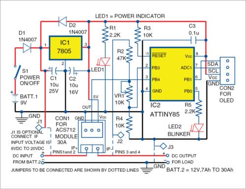
The circuit can measure maximum voltage up to 30V DC and maximum current up to 30A DC. To avoid damaging the microcontroller (MCU), measurements should be limited to 30V and 30A. If the value exceedes 30V, the display shows OFLO, which indicates overflow of the parameter.
ATtiny85
ATtiny85 is an eight-pin MCU sufficiently powerful for the project, with 8kB flash, 512B RAM, 512B EEPROM and 1MHz default clock frequency at the heart of the system. It continuously measures voltage and current through its two ADC channels. ADC values are processed and converted to voltage, current and power values, and then displayed on the OLED.

ACS712
The current-sensing module uses Allegro’s ACS712 chip, which uses Hall effect to convert current to voltage. Output of the module is fed to one of the ADC channels of the MCU. A 30A module is used for measuring current. Sensitivity of the module is 66mV/A (refer ACS712 data sheet).
OLED
It is a small display measuring 2.4 cms with 128×64-pixel resolution, 5V DC supply and I2C connector. It has four pins, out of which one is for serial data (SDA pin), another for clock (SCL pin) and the remaining two for power supply.
To show text on the display, 64 rows of pixels are divided into eight text rows with eight-pixel rows in each text row. To display text clearly, code is set for sixteen-pixel height and eight-pixel width. So, OLED can display text in four rows with 16×8 font size.

Accuracy of ACS712 may slightly vary from module to module. Multiplication factor is initialised as 740 in the source program, which is achieved from 66mV/A (as per Allegro’s data sheet). The value may be varied in the source code (vaw_meter.c), declared as int MF=740.
Then, re-compile the code using AVR studio and upload vaw_meter.hex file to the MCU.
Construction and testing
After assembling the circuit on the PCB or veroboard, burn vaw_meter.hex to ATtiny85 MCU using any AVR programmer. Insert the programmed ATtiny85 to its eight-pin socket/base. Connect the OLED (four-pin) to the circuit at connector CON2. Power on the board with 9V battery (Batt.1) via switch S1.
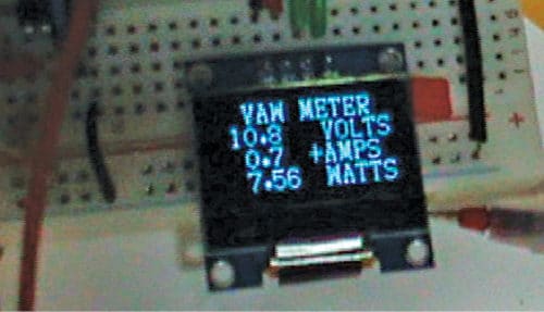
Power indicator LED1 will be on. LED2 will start blinking, indicating that program initialisation is complete and the circuit is ready for use. Now, the OLED will start displaying volts, amps and watts after a short delay.
Next, connect 12V battery (Batt.2) at DC input pins. Adjust VR1 to display the same voltage on the OLED. Connect jumper wires J2 and J3 externally to positive DC output and ground, respectively. J1 is optional and should be connected to positive DC input only when 8V DC to 20V DC power supply is used.
Connect 12V bulb (used in automobiles) as load or any load at DC output pins. The OLED displays current and power consumption. The + and – symbols in the OLED display prefixed to AMPS indicate the direction of current with respect to ACS712 module terminals (IP+ and IP-), as shown in the circuit.
In case 8V to 20V is used for measurement, connect J1 to positive DC input to get the power supply to the circuit from 12V battery. Remove 9V battery in that case.
Download source folder: click here
Fayaz Hassan is manager at Visakhapatnam Steel Plant, Andhra Pradesh. His interests include MCU projects, mechatronics and robotics


Schematic shows SDA connected to PB1 (PIN6), however datasheet for ATtiny85 shows defaults for SDA=PB0 (PIN5). My question: How did you reprogram/redefine SDA to PB1? That is either a super nice programming trick which I haven’t learned yet, or otherwise the schematic shown has an error (which I doubt). I would love to know how you redirected/reprogrammed/redefined physical PIN6 to perform function of SDA.
Check to see if the code will compile as things are here. There’s a similar circuit on this site for a zener diode tester which I have ready on a board to use IF I could just get the code to work as posted on the page. For some reason I am having issues with getting even the LED blink code functioning and I have code for much more complex code for projects in my AVR suite which I know worked before my system got hacked a few years back. I can’t even get a BLDR file to fly right now for bringing chips up to load code on and I don’t know why.