
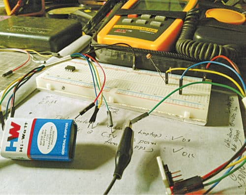
 The minuscule LED night marker presented here is an automatic light beacon that wakes up at night, or when there is not enough ambient light in its environment. Anyone active in the dark (walking, riding, swimming, etc) can utilise this portable marker as a safety device to put a clear and distinct mark in darkness. The author’s prototype is shown in Fig. 1.
Circuit and Working
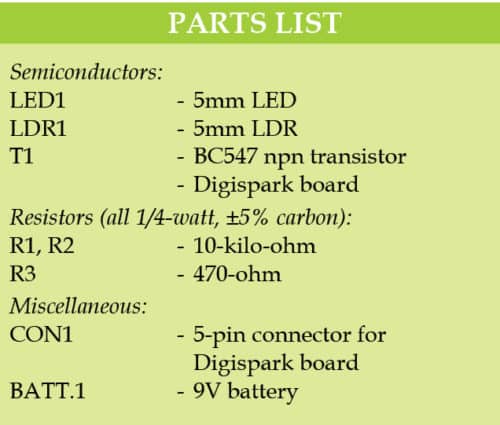
The circuit diagram of the LED night marker is shown in Fig. 2. It consists of Digispark board, 9V battery and a few other components. At the heart of the circuit is Digispark Attiny85 board. Digispark board connectors are represented by connector CON1. Hardware is powered by 6F22 (9V) alkaline battery through Vin pin. An external indicator (LED1) is used by enabling a low-power driver wired around the small signal transistor BC547 (T1).
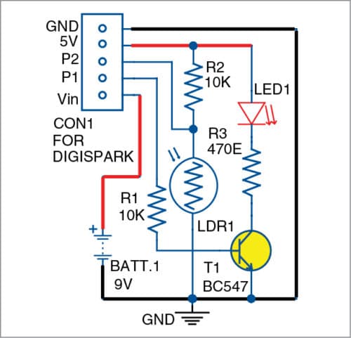
The photo resistor (LDR1) connected to analogue input pin P2 of the board is used to control external LED1 marker through onboard pin P1, which blinks when there is not enough ambient light.
The program (night_marker.ino) is written in Arduino programming language. A connector is provided in Digispark board as a USB interface to program it through Arduino IDE on the computer. Also, the little code is well-commented, which allows easy modification as per requirement.
Construction and testing
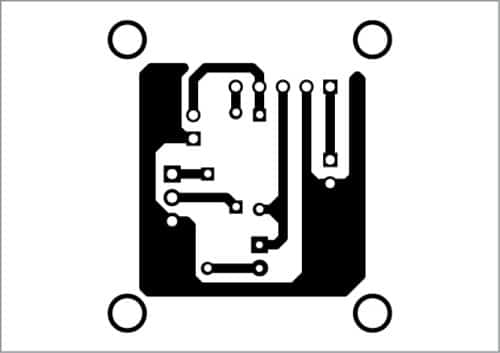
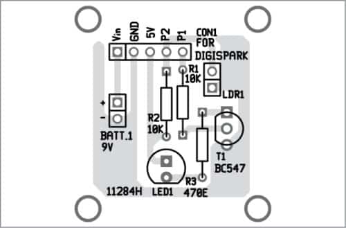
A PCB layout of the LED night marker is shown in Fig. 3 and its components layout in Fig. 4. Assemble the components on the PCB as per the circuit diagram.

Download PCB and Component Layout PDFs: Click Here
Download Source Folder
The breadboard prototype was tested with a 9V battery (6F22), which worked well with current consumption of just above 20mA in idle state (>200 lux) and just below 25mA in active state (<10 lux). A 2S lithium-ion/lithium-polymer battery (7.4V) is recommended in lieu of 6F22 9V battery. Make sure that the battery is connected with correct polarity, as incorrect battery input could fry Digispark board.
Enclose the finished device in a waterproof, transparent/translucent box, preferably with a power on/off switch (not shown in the schematic). Drill adequate holes on the front/top panel of the enclosure for mounting LDR1, LED1 and power switch. In addition, add a rectangular window on one side of the box for the USB connector of Digispark board.

T.K. Hareendran is founder and promoter of TechNode Protolabz


Can electronicsforu.com help on CD door open and close tutorial using transistorize circuit.