This system can be used in offices or hotels to call an attendant from seven different locations. The circuit provides audio indication of the calling location to the attendant on a speaker, and video indication through a seven-segment display. The locations are provided with separate switches to log requests for the services of the attendant.
Fig. 1 shows the circuit, which is built around transformer X1, voltage regulator 7805 (IC1), eight-input priority encoder IC CD4532 (IC2), shift register 74LS96 (IC3), triple three-input OR gate CD4075 (IC4), BCD to seven-segment decoder/driver 74LC47 (IC5), common anode seven-segment display LTS542, melody generator UM66 and a speaker, along with some discrete components. The circuit can be divided into four sections.
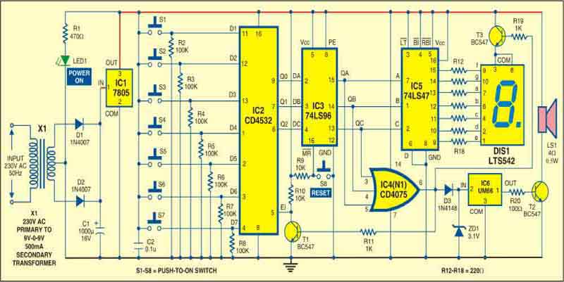
Power supply section. To derive power supply for the circuit, the 230V, 50Hz mains is stepped down by transformer X1 to deliver a secondary output of 9V-0-9V, 500mA. The secondary output of X1 is rectified by a full-wave rectifier comprising diodes D1 and D2. It is filtered by capacitor C1 and regulated by IC 7805. The regulated 5V obtained is used to power the circuit.
Input logging section. Switches S1 through S7 are interfaced as input to the system through IC 4532. For loading the input data through switches to the IC2, enable interrupt (EI) pin 5 of IC2 must be high.
Register and control section. It is used to store the binary output of the encoder until it is reset. To reset the data stored on the shift register, press reset switch S8 momentarily. For controlling the input data, a three-input OR gate IC CD4075 is used. The high output of IC4 is used for switching transistors T1 and T3. Transistor T3 is used to control the display LTS542 (DIS1) and transistor T1 is used to latch input data by keeping pin 5 of IC2 low.

Display and melody section. It is built around decoder driver 74LS47, a common anode seven-segment display LTS542 and melody generator IC UM66. DIS1 is driven by IC5. The input of a particular location is shown on DIS1. IC6 and transistor T2 are used to drive the loudspeaker. The audio output is obtained from the loudspeaker when you press any switch from S1 through S7.
Working of the circuit is simple. When any of the seven callers presses the switch (S1 through S7), respective binary code is generated at the output of IC2, which is further given to IC3. These binary codes at data pins 2, 3 and 4 of IC3 ensure that at least one of its output pins-13,14 or 15-is high. This makes the output pin 6 of OR gate (N1) high, which performs three task:
1. Provides power supply to seven-segment display DIS1 to display caller’s number through transistor T3.
2. Blocks the acceptance of further input due to low voltage at EI pin 5 of encoder IC2, as transistor T1 conducts.
3. Provides input power supply to IC4 to produce sound to alert the attendant.

After the attendant responds and presses reset switch S8 momentarily, all the outputs of IC2 go low. This makes the output of OR gate IC4 low. This, in turn, results in cutting off the power supply to the seven-segment display and melody generator IC6. The encoder IC2 is permitted to accept next input through switches S1 through S7 by providing high voltage to its EI pin 5.
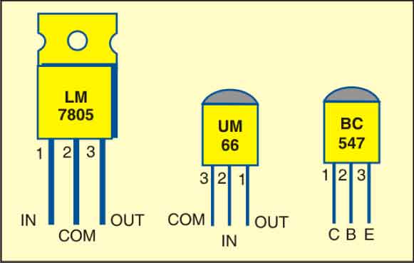
Assemble the circuit on a general-purpose PCB. Refer Fig. 2 for pin configurations of ICs 7805, UM66 and BC547. After assembling the circuit, enclose it in a suitable cabinet along with reset switch S8, DIS1 and speaker, and place it in the attendant’s room. Extend all switches, S1 through S8, to respective rooms using two-wire cables for each switch. Fix the transformer inside the cabinet. Fix power-on LED1 at front panel of the cabinet. Connect a power cable to the primary of the transformer for providing the mains supply to the circuit.
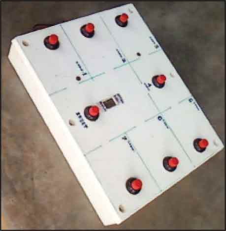
Alternatively, if you wish to demonstrate the circuit as a project, the switches can be fixed on the the top of enclosure as shown in author’s prototype (Fig. 3).