
 This simple delay timer circuit is used to prevent noise and spike in electrical equipment before switching on the main input supply. Most electrical appliances powered by 230V AC mains produce large voltage spikes when the power is switched on. The voltage spike also affects low-power electronic circuits. Hence, noise suppression and spike protection are very important. One of the easiest solutions is to use a power-on delay circuit that switches on the electronic circuit after a few seconds.
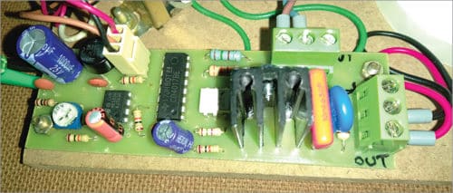
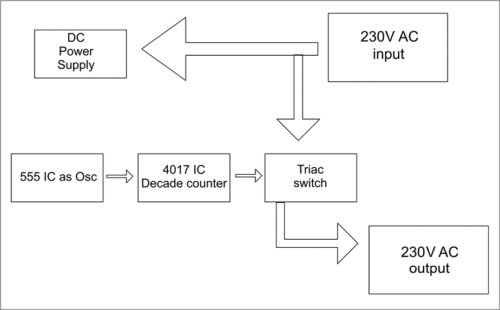
The author’s prototype is shown in Fig. 1. Block diagram of the power-on delay timer circuit is shown in Fig. 2.
Circuit description
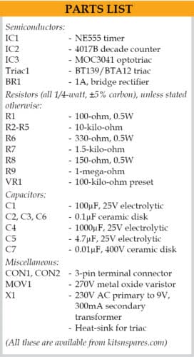
Circuit diagram of power-on delay timer circuit is shown in Fig. 3. It is built around a timer NE555 (IC1), decade counter 4017B (IC2), optotriac MOC3041 (IC3), triac BT139 (TRIAC1), a 100-kilo-ohm preset (VR1) and a few other components.
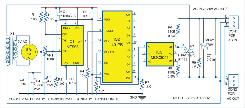
Timing accuracy is achieved by using decade counter 4017B. NE555 IC is used as a bistable oscillator. VR1 preset is used to vary the timings from 0.1-sec to 1-sec pulse in NE555 IC. When the main power is switched on, 4017B starts counting the pulses received from NE555. The output pulses from NE555 are fed to clock input pin 14 of 4017B. As a result, 4017B gets breezed and its ten outputs (Q0 through Q9) become high sequentially. Output pin 11 (Q9) of 4017B goes high at 10th pulse received from NE555.
The output is built around triac BT139, which can switch up to 16-ampere AC load. The maximum 16-ampere current means we can have 60 per cent as optimum current, that is, up to 9.6 amperes (or 16×0.6=9.6 amperes). The optimum load will be 220V×9.6A=2112 watts. The triac is triggered by optotriac MOC3041 (IC3). Optotriac has the advantage of triggering 230V AC power by itself and providing circuit isolation.

DC power for this circuit is derived from step-down transformer X1, bridge rectifier BR1 and capacitors C3 and C4. Resistor R2, capacitor C5 and preset VR1 are timing components for NE555 IC. You can change the delay time (0.1 to 1-sec) of this circuit by varying VR1.
During power-on, clock enable pin 13 (CLK EN) and pin 11 (Q9) of 4017B are in low states. Each output of 4017B goes high one by one after each clock pulse. When Q9 goes high with tenth pulse, CLK EN also goes high. This stops the counting process in 4017B. The current high output states of 4017B remain high till the power is off. High state at Q9 makes MOC3041 to conduct. This triggers the main triac BT139 and the AC supply for the load becomes available across connector CON2.
To improve the life of triac, the spike arrester circuit built around resistor R9, metal oxide varistor MOV1 and capacitor C7 is used.

Construction and testing
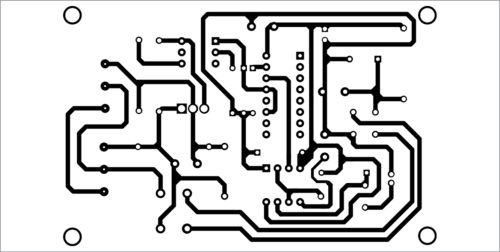
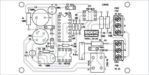
A PCB layout for the power-on delay timer is shown in Fig. 4 and its components layout in Fig. 5. After assembling the circuit, connect the 230V, 50Hz AC supply across CON1. AC load should be connected across CON2.
Download PCB and Component Layout PDFs: click here
For initial testing, remove IC3 from the circuit and connect an LED across pins 1 and 2 of MOC3041. Switch on the delay timer circuit. The LED should glow after a delay. If LED does not glow, check voltage at pin 3 of NE555 with multimeter. If voltage pulses are available at pin 3 of IC NE555, check 4017B and its associated components.
If LED glows after a time delay, your circuit is working well. Now, remove the LED and insert the optotriac MOC3041, triac BT139 and associated components. The power-on delay timer is now ready for use.
A suitable heat-sink is recommended for triac BT139. You may use BTA12 in place of BT139.
S. Thangamani is electronics reverse engineer with 38 years of service in the electronics industry. He is the proprietor of Parvaty Electronics, Madurai and vice president, Tamil Nadu Electronics Technicians Association


Make in India almost possible with us for everything in electronics manufacturing
I have a our Requirements in timer dealy in pcb type and buzze sounds function
Kindly elaborate on your query.
thank you for sharing but please i would want to build this circuit kindly assist me with the pcb size(dimensions)
zeb.
Thanks for the feedback! The given PCB layout is actual size single-sided PCB. You can draw it using free software such GEDA software or limited version of Eagle software.
Sir, it is possible to get a GERBER file for this project
Thank you for your continue support.
Please send your request on Gerber file to [email protected]
With help of an electronic technician, I am building a tube amp of 40 watts per channel, I wish to install (1) time delay and (2) soft start circuit in this amp. If your PCB is available for purchase, I will be willing to buy 2 nos.
My technician is based in Chennai.
Or please advise me where in india I can buy such PCB.
Thanks
Sharad Patel
Ahmedabad