 Most laboratories and educational institutions are in need of precision stopwatch for accurate time measurement. This simple DIY project focuses on the construction of a stopwatch with 0.01-second accuracy. The stopwatch can be used for recording lap times in sports events by connecting a sensor across connector CON2.
Stopwatch circuit and working
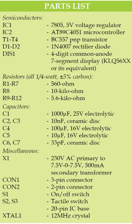
The circuit diagram of the precision stopwatch is shown in Fig. 1. It is built around 7805 voltage regulator (IC1), AT89C4051 microcontroller (IC2), 4-digit common-anode 7-segment display (DIS1) and a few other components.

The circuit is powered from 230V AC mains via step-down transformer X1 (not shown here). X1 output (7.5V-0-7.5V AC) is rectified by diodes D1 and D2 and smoothened by capacitors C1 and C4.
Rectified DC voltage is regulated to 5V by 7805 and fed to the microcontroller circuit. The controller (IC2) runs at an oscillator frequency of 12MHz. This is achieved by connecting a 12MHz crystal across XTAL1 and XTAL2 pins of IC2.
Switch S1 is the power on/off switch for the circuit. Capacitors C2 and C3 are used for suppressing high-frequency signals generated by IC1. Capacitors C6 and C7 are decoupling capacitors for crystal. Capacitor C5, and resistor R8 forms a part of power-on reset circuit for IC2.

Switch S2 is used as manual reset for IC2 and to reset the counter to zero. S3 is used to start and stop the countdown timer. A 4-digit multiplexed 7-segment display is used for hardware simplicity and economic benefits. Fig. 2 shows pin details of the 4-digit common-anode 7-segment display.

When S1 is closed, DIS1 indicates 00.00. On pressing S3, DIS1 starts counting up until S3 is released. DIS1 indicates the last count value till S2 is pressed. Maximum count given by DIS1 is 99.99 seconds.
Software
The software (stopwatch.c) is written in C language and compiled using Keil µVision V5 software. Delay in C language depends on the compiler. Sometimes, a small correction may be required on the delay loop for calibration purpose.

The hex code generated by Keil software is burnt into the microcontroller using a suitable programmer. A Topview Programmer was used for programming the microcontroller during testing. You can use any suitable software for programming the microcontroller.
Download source code
Construction and testing
A single-side PCB layout for the precision stopwatch is shown in Fig. 3 and its components layout in Fig. 4.


Download PCB and component layout PDFs: click here
After assembling the circuit on the PCB, cross-check for any wrong connections. After burning the hex code into AT89C4051, place it on the PCB using an IC base. Fit the PCB, switches, connectors and DIS1 in a general-purpose cabinet.
Switch on the unit by closing S1. Ensure that DIS1 shows 00.00 reading. If not, check the circuit for any mistake(s). When you close S3, the display starts counting—open S3 and the counting stops.
If S3 is closed again, the display starts counting from the last count value. Compare the reading with a calibrated stopwatch. If there is a mismatch in the reading, adjust the delay loop in the code till exact timing is attained. At any time, press S2 momentarily to reset the display.
For a simple application, calibration may not be necessary, but for laboratory use, it is recommended to calibrate the unit. A Stopwatch can measure elapsed time for one interval, or the total of elapsed time across multiple intervals.
CON2 is provided for replacing S3 with an external switch or sensor.