
 In the DPDT (double pole double throw) based joystick or the RF transmitter module switch based joystick, you must press two buttons simultaneously for a robot to move forward, backward or in circle. In this one, you can press one button for one motion very similar to a normal joystick. You need not practice controlling the robot as you do when you use a DPDT based joystick. This joystick circuit is quite cheaper than the joysticks available in the market. You only have to connect it to a RF transmitter module and make the supply common.
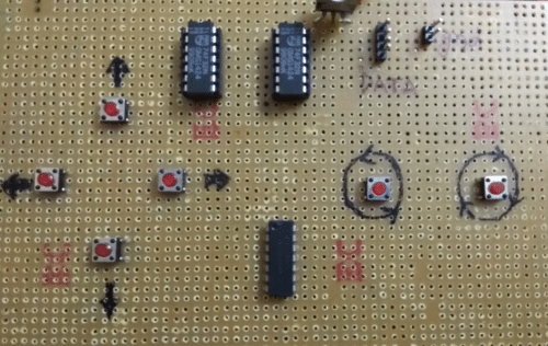
Author’s Prototype
Components Required
| S.NO. | COMPONENT NAME | QUANTITY |
| 1 | ZERO PCB | 1 |
| 2 | 7432(OR GATE IC) | 2 |
| 3 | 7404(NOT GATE IC) | 1 |
| 4 | PUSH BUTTON | 6 |
| 5 | 1K (RESISTOR) | 6 |
| 6 | LED | 6 |
| 7 | 330 OHM | 1 |
| 8 | HEADER PIN MALE | 6 |
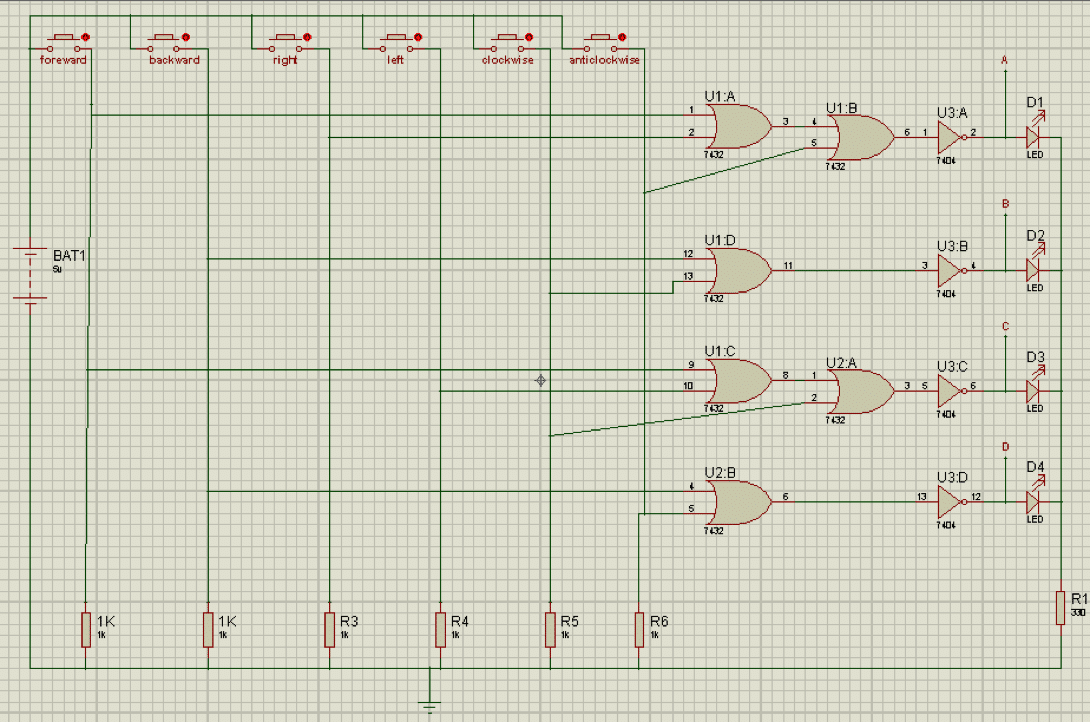
Circuit Diagram
Setting up the Circuit
I noted down the logic needed for each move like forward, backward, left, right, clockwise and anticlockwise rotation and made a truth table based on that truth table I designed the circuit which is nothing but a circuit of 6*4 Encoder circuit, on pressing any of six button a BCD code is generated which is for certain move. You may think why I have not used 16*4 encoder IC or 3 input OR gate IC. It’s simply because it is difficult to find in the market.
| S.NO. | MOTION | A | B | C | D |
| 1 | FORWARD | 0 | 1 | 0 | 1 |
| 2 | BACKWARD | 1 | 0 | 1 | 0 |
| 3 | RIGHT | 0 | 1 | 1 | 1 |
| 4 | LEFT | 1 | 1 | 0 | 1 |
| 5 | CLOCKWISE ROTATION | 1 | 0 | 0 | 1 |
| 6 | ANTICLOCKWISE ROTATION | 0 | 1 | 1 | 0 |
Circuit operation
Whenever any input of OR gate goes HIGH its output will be HIGH and NOT gate output will be HIGH when input is LOW, and LOW when input is HIGH. Initially every gate used in circuit is pulled down to zero by pulldown resistor 1K. Suppose forward button is pressed as shown in circuit diagram it will make U1:A (OR gate) go HIGH which will make U1:B(OR gate) go HIGH also it will make U1:C (OR gate) go HIGH which will make U2:A(OR gate) go HIGH before passing not gate code generated is 1010 but after passing through not gates it become 0101 which is required logic to move forward as you can see in the truth table.
Similarly when we press backward button as in circuit diagram it will make U1:D and U2:B (OR gates) go HIGH, here before passing not gates code is 0101 after passing not gate it become 1010 which is required condition for moving backward, led will glow according to the code it will glow indicating HIGH else LOW. Match the each output with truth table and then connect the RF transmitter module with it. In RF transmitter module 4 switches are given connect the output of circuit A, B, C, D to that switch and make the supply common.

Tutorial Video
If you have any doubt you can watch a video at:
