
 How many times do we use an electric switch in a day? So often that it has become secondary nature and no one keeps a count. The mechanical switch, which is flipped or pushed to make or break a connection, has been the standard all these years. But times have changed and touch switches are the new trend. Unlike the mechanical switches which are easily damaged by dirt, moisture or mishandling, touch switches are encased making them resilient to the toughest environment. The current designs of touch switches make them aesthetically pleasing and blend with the room decor.
Touch switches can be of different types
Resistive – The switch operates by measuring the change in resistance between two contacts when they are touched simultaneously. Such switches are comparatively easy to make and can be implemented by having touch plates connected to the base of a Darlington pair transistor (see project in EFY December, 2017 issue) or the gate of a N-channel Mosfet.
Piezo ceramic – Piezo touch switches sense displacement of charge due to compression of the piezo element and can be embedded in any kind of material including stiff materials like stainless steel.
Capacitive – A capacitive sensor works by detecting a change in capacitance due to the influence of an external object.
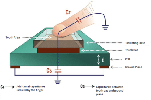
A capacitive sensor can be made on a double sided PCB by regarding one side as the touch sensor and the opposite side as the second plate of the capacitor. When voltage is applied across these plates, the two plates get charged. In the equilibrium state the plates have the same voltage as the power source. Capacitance is a measure of charge per volt (Cs=Q/V). When a finger is moved near the sensor plate, the electric field around the capacitor plate polarises the human body and energy gets transferred to it. This causes more charge to flow to the sensor plate till another equilibrium state is reached. This increases the charge concentration on the sensor plate causing a change (increase) in capacitance.

It is not necessary to physically touch the sensor plate as a disturbance of the electric field near the sensor is enough to induce a change in capacitance. The sensor plate can, therefore, be placed behind a protective overlay. The induced capacitance is determined by the equation
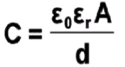
where, Er is the dielectric constant of the insulating plate and d its thickness. The dielectric constant of glass ranges between 3.8 and 14.5 while that of plexiglass (acrylic) is between 2.6 and 3.5 Wood has a dielectric constant between 1.4 and 2.9. As such, glass is the best material for the protective overlay followed by plexiglass.

While designing the touch sensor PCB, the following points should be kept in mind
- The ground plane plate should not overlap the sensor pad but shifted from under the touch pad. This results in lower capacitance but higher sensitivity as the electric field is projected further in the air.
- The touch pad should not be unnecessarily large as a smaller plate has a higher charge density and therefore a stronger electric field than a larger plate. A recommended size is the size of a finger tip, say 15mm * 15mm.
- The length of the track from the touch pad to the input pin of the detector should be as short as possible. The tracks should also not be parallel or cross other tracks.
- The detector circuit should have a low signal to noise ratio.
- If more than one switch is accommodated on a panel, the space between two pads should be large enough so that two adjacent touch switches are not triggered with one touch.
The detector circuit has an oscillator, the frequency of which is dependent on the capacitance of the touch pad. When a finger is moved close to the touch pad, the additional capacitance induces a change of frequency of the internal oscillator. The detector circuit tracks the oscillator frequency at timed intervals and when the shift crosses the threshold change, the circuit triggers a key press event.
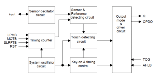
Keeping the above design considerations in mind, it is better to uses a specialised detector IC. Tontek Design Technology Ltd, a Taiwanese company makes a series of touch pad detector ICs. TTP223 is a one touch key pad detector IC while TTP224 and TTP225 can manage 4 or 8 pads respectively.
The block diagram of the TTP223 IC is shown below
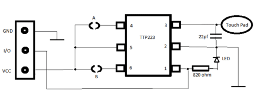
The equivalent connection diagram for the IC is as under
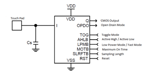
The capacitance Cs is added to adjust the sensitivity. The lower the value of Cs, the higher is the sensitivity. The range of Cs value is 0 to 50pF.
The IC is available in different packages having 16 pin, 8 pin or 6 pin configurations. Since we will not be using most of the control pins and go by their defaults, we have used the 6 pin version. The pin-out is shown in figure 4.
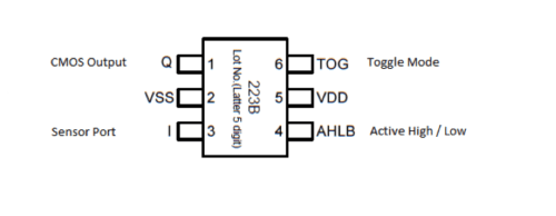
Settings available for this package are:
Pin 4 – AHLB – The output is active high when this pin is held open and is active low when this pin is connected to VDD
Pin 6 – This pin determines the mode of operation. The output remains in its active state as long as the touch pad is kept touched if this pin is held open and operates in toggle mode if this pin is held high.
Prebuilt modules built around this single touch pad detector IC TTP223 have been used in this project. These modules are available easily on online portals.
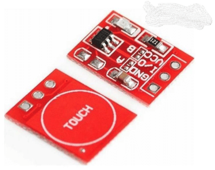
The circuit diagram of the module is shown in figure
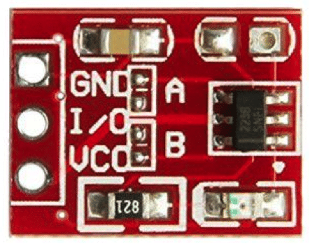
The module has two pads (A and B) which can be shorted to change the behavior of the module. As the relay module used has active low inputs, the following settings have been used
| Mode | Pad A | Pad B |
| Normal on/off switch | Shorted (for low active output) | Shorted (Toggle mode) |
| Press Button Switch | Shorted (for low active output) | Open |
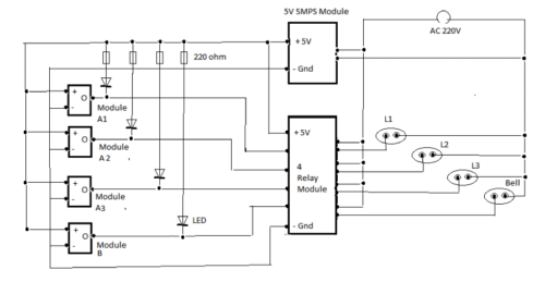
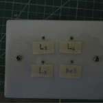
In the current project we have built a panel of four “touch” switches, three of which function like normal on/off switches while the fourth works as a momentary switch (bell switch). The onboard LEDs have been removed as they glow when the output is in the low state (which indicates the “off” position in our case) and replaced with external 3mm LEDs to show the “on” state.
In practice, I found it very difficult to short the pads A and B with solder, but found shorting pin 4 or 6 to pin 5 easier.
The connection diagram of the panel is shown in figure
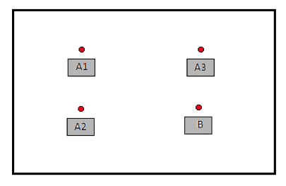
A suggested layout of the panel is shown at figure
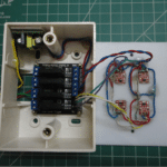
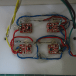
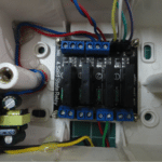
The modules were stuck to the underside of the acrylic sheet using hot glue. The relay board and 5volt power supply module were accommodated inside the switch box. The external lights and bell were connected to the relays.
| List of Parts | |
| TTP223 Touch Module | 4 nos |
| 3.3 V or 5V 700ma Power module | |
| 4 channel Relay Board | |
| Switch Box | |
| Acrylic Sheet | |
The switch board is now ready and replace a regular switchboard. The relays used in this project use solid-state relays which can handle a maximum of 2amps current and are suitable for room lights. The relay board can be replaced with regular electro-mechanical relays which can handle higher current (10A).
The number of touch pads can be increased/decreased depending on the number of switches required. The TTP223 IC can handle voltages between 2.0V to 5.5V and power supply should not exceed 5.5 volts.
To make the switchboard more attractive, the front panel can be built using two pieces of transparent 1.5mm thick acrylic sheets instead of one 3mm thick sheet. A paper with a printed pattern can be sandwiched between the two sheets to give it a professional look.
Photos of the completed unit


Buonasera, desideravo creare con questi pulsanti TTP223 dei deviatori, non ho trovato nulla a riguardo nel web.
Pensate sia possibile. Grazie buona serata
Grazie