
 Remote wireless display of sensor data is required in many industrial and consumer applications. Sensor data like light, temperature, accelerometer and strain gauge data, etc can be communicated through Wi-Fi and displayed on a mobile phone, laptop, or desktop PC depending on application and convenience.
This project uses NodeMCU for this purpose, which is a single-board microcontroller board having Wi-Fi chip ESP8266. Hence it is good for IoT applications. NodeMCU has open-source hardware and firmware that uses Lua scripting language. It has following features:
- One analogue input (10-bit integrated ADC)
- Thirteen digital I/O pins (alternate functions like USART/I2C/SPI)
- Micro USB port for power, programming, and debugging
- A 2×2.54mm, 15-pin header with access to GPIOs, SPI, UART, ADC, and power pins
- Reset and flash buttons
- 5V power supply through the micro USB port
- Wi-Fi support (802.11 b/g/n, 2.4GHz, WPA/WPA2)
- Integrated low-power 32-bit RISC MCU (L106)
- 64KB instructions RAM, 96KB data RAM
- Integrated TCP/IP protocol stack
- Integrated TR switch, balun, LNA, power amplifier, and matching network
- Integrated PLL, regulators, and power management units
- Supports antenna diversity
- Standby power consumption of <1.0mW
- +20dBm output power in 802.11b mode
- Operating temperature range of -40°C to 125°C
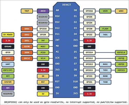
The pin diagram of NodeMCU is shown in Fig. 1.
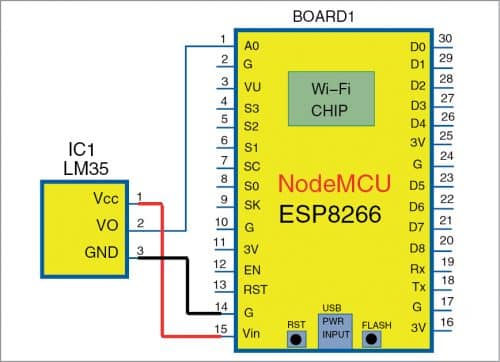
The circuit diagram to measure and monitor temperature remotely is shown in Fig. 2. Parts list for the circuit includes NodeMCU ESP8266-12 board and an LM35 sensor or digital/analogue I/O board. NodeMCU is used as a web server that measures temperature and broadcasts the sensor data on the Internet browser. Software The NodeMCU board can be programmed with Arduino IDE or MicroPython firmware. Install Arduino IDE and NodeMCU support using Boards Manager. This installation process using Arduino was published in ‘Control With Authentication for Up to Four Devices’ DIY article in April 2019 issue of EFY magazine.
MicroPython allows you to run miniature version of Python 3 on embedded boards and microcontrollers. It is a tiny open source Python programming language interpreter designed to run on small embedded devices. MicroPython does not support entire Python standard library, so we can call it a sub-set of Python.

Advantages of MicroPython include small footprint (requires less memory), it is near the hardware due to Hardware API, and is a clean and simple Python code to control hardware. Disadvantages include limited standard library functions and execution speed less than of C language. So sometimes it may create problem for real-time signal processing where execution speed requirement is critical.
There are two methods to install MicroPython firmware in NodeMCU. Use any one of the following methods (ESP8266 flasher and ESPtool) to upload MicroPython firmware to your NodeMCU.
ESP8266 flasher
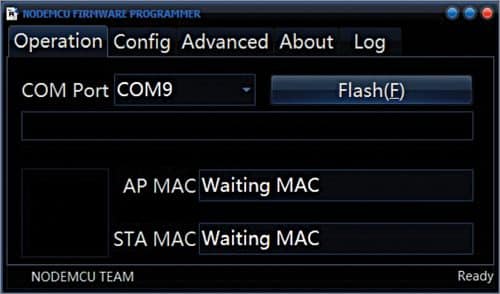
Download nodemcu-flahser. Download binary file esp8266-20170823-v1.9.2.bin (or the latest version). Click ESP8266Flasher in nodemcu-flasher unzip folder, select binary file esp8266-20170823-v1.9.2.bin firmware, and click on Flash as shown in Fig. 3. This will install the firmware in NodeMCU board. ESPtool command. Use ESPtool in command prompt. Following commands are used in Windows 7, 64-bit machine with Python 3.

Open command prompt (cmd) and install esptool using following command: >pip install esptool
First connect NodeMCU board to your PC and erase it using following command:
>esptool.exe –p COM9 -b 115200 erase_flash
Change COM9 port depending on COM port assigned to the NodeMCU after connecting it with your PC/laptop.
Next, download firmware to NodeMCU using following command:
> esptool.exe –port COM9 –baud 115200
write_flash –flash_size=detect 0 esp8266-20170823-v1.9.2.bin
In above command, give the path of binary file for the firmware (if it is not there in the same directory), use flash_size=detect if ROM size is unknown. (Above command can be written as batch file.)
Now, download ESPlorer software
ESPlorer software (Java based) is used to upload MicroPython application source code to NodeMCU. Steps to upload MicroPython program to NodeMCU through ESPlorer are:
- Start ESPlorer. Go to Settings and select MicroPython option.
- Select the Scripts option.
- Connect NodeMCU and select corresponding COM port, set baud rate to 115200.
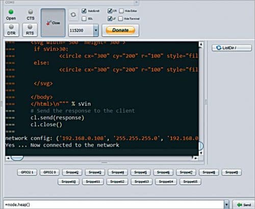
- Open the port and press reset button on NodeMCU. Command prompt will display on the right as shown in Fig. 4.
- Open new file and write your program code, or open the Python script (ReadTemperatureDisplayOnBrowser.py)
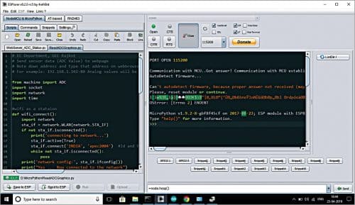
After writing the above Python script, press ‘Send to ESP’ button as shown in Fig. 4. NodeMCU will be connected to the Wi-Fi network. Note down the IP address 192.168.0.108 as shown in Fig. 5. Enter the same IP address in above Python program and press ‘Send to ESP’ button once again to upload the Python code to NodeMCU.
This project has also been successfully tested using Thonny IDE. The steps to use NodeMCU with ESPlorer and Thonny IDE are included in the source code folder.
Construction and testing
Connect temperature sensor LM35 with NodeMCU board with the help of three wires as shown in the circuit diagram (Fig. 2). You can also use the LM35 sensor available on a digital-analogue I/O module to test the project.
Open any web browser on PC (or smartphone) and enter the URL displayed on command prompt of ESPlorer as shown in Fig. 5. Ensure that the PC is connected to the
same network access point where NodeMCU is connected.
If temperature is greater than 40°C, onboard LED of NodeMCU will glow and the circle displayed on web browser will become red. If temperature is less than or equal to 40°C, the LED will be off and the circle will become green. The screenshot of temperature display on a PC’s web browser is shown in Fig. 6.
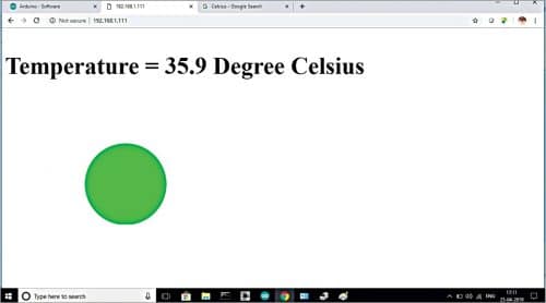
In the current source code, you need to press F5 (refresh) button on the PC to get new value of temperature on the browser. You can enter the same IP address on the smartphone and get the same temperature display.
Digital-analogue I/O module
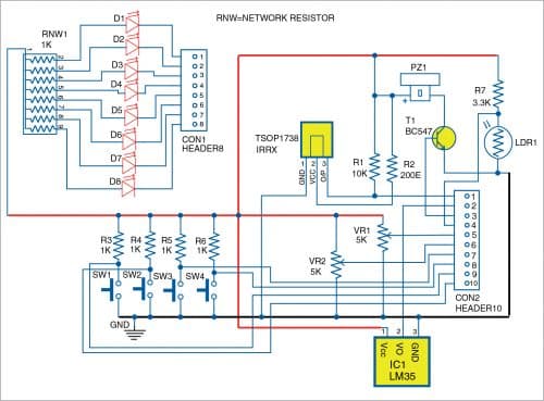
The layout of a digital-analogue I/O (DAIO) module is shown in Fig. 7 and its schematic diagram is shown in Fig. 8. DAIO module has the following:
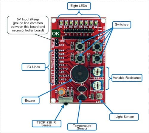
Digital inputs for any microcontroller. Four switches and infrared receiver TSOP1738
Analogue inputs for any microcontroller. Two variable resistors, one light sensor, and one temperature sensor
Digital and analogue outputs for any microcontroller. Eight LEDs and a buzzer
Three female-to-female connectors are required to connect LM35 sensor of DAIO module to NodeMCU board. The Vcc terminal of DAIO module should be connected to 3.3V and its ground pin to ground pin of NodeMCU board.
Download Source Code
Dr C.H. Vithalani is professor in Electronics and Communication Engineering Department at Government Engineering College, Rajkot (Gujarat). He has guided 16 PhD scholars and published 25 research papers. Solving real-life challenges by mentoring innovative student projects is his hobby.
Please note: If you are unable to download the source code, please try to open the page in incognito mode and retry or temporarily turn off the antivirus before downloading.


