

Smart cellphone guard presented here is in fact a simple infrared (IR) sensor alarm secures your cellphone with an invisible beam of light that will trip an alarm if anyone tries to lift the handset from its dock!
Cellphone guard circuit
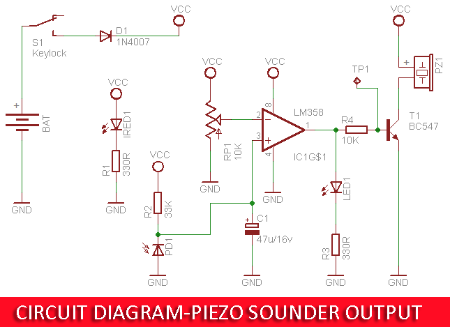
From the circuit (fig. 1) you can see that the cellphone guard uses a generic infrared sender-receiver combination (IRED1 & PD1) to watch the presence of a cellphone in the dock, and the popular dual-op-amp chip LM358 (IC1) takes care of the alert signal generation. This is made visible via a red led (LED1). This needs to be fed to a piezo-sounder (PZ1), which happens via a driver transistor BC547 (T1). The system is 6V powered by a series of four 1.5V cells (BAT) with a silicon diode 1N4007 (D1) acting as a reverse polarity protection. The 10K preset (RP1) provides sensitivity adjustment of the detection circuit.
Components List
• IC1: Op-Amp IC LM358N
• IRED1: Infrared LED 5mm (TSFF5210 or equivalent)
• PD1: Infrared Photo Diode 5mm (BPV10NF or equivalent)
• D1: Silicon Diode 1N4007
• LED1: Light Emitting Diode 5mm Red
• T1: NPN transistor BC547 (or equivalent) – see text
• R1, R3: Resistor 330R ¼ w
• R2: Resistor 330K ¼ w
• R4: Resistor 1K ¼ w
• RP1: Multi-Turn Preset Pot 10K
• C1: Electrolytic Capacitor 47uF/16V
• PZ1: Piezo-Sounder/Piezo-Buzzer 5V – see text
• S1: Keylock Switch
• BAT: 6V Battery (1.5Vx4)
Construction Tips
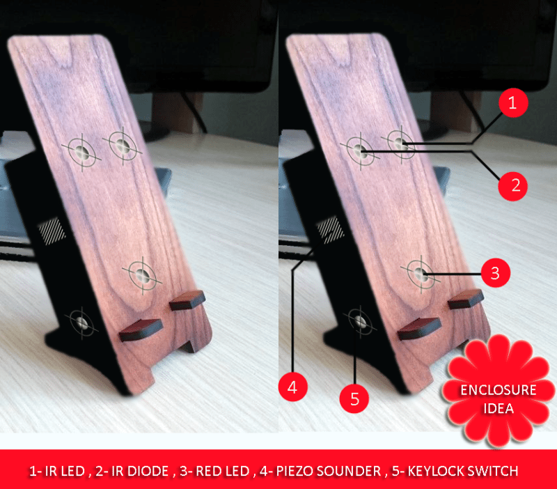
The entire circuit assembly assembled on a small circuit board (together with four penlight cells) should be fitted in an appropriate homemade enclosure, although a readymade cellphone holder is a good alternative. The keylock switch must be fitted directly to the rear/side of the enclosure as it should only be necessary to access it privately. Battery holder (also the piezo sounder) can connected by flying leads to the pads on the circuit board. The infrared components of course be mounted on the front where it can be ‘see’ the cellphone in the dock. The layout is not especially critical, what you need to ensure is that the dock can support most cellphone handsets (fig 2).

Initial Setup
As stated, the multiturn preset pot determines the threshold level that triggers the warning. After construction, power up the system and adjust RP1 to make LED1 turn on when the there’s no cellphone in the dock. In that state, you can see a voltage around 3.6V at pin 1 of IC1, with respect to 0V (GND) rail.
Supplement
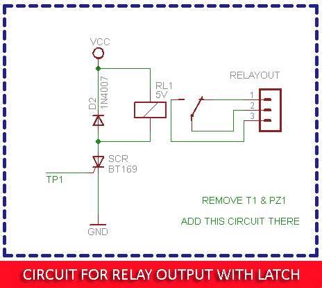
If you’re using a black-colored cellphone, remember, a matte black surface does not register with the sensor, as the black surface doesn’t reflect infrared light very well. So try to attach a small white/reflective sticker at the back cover of your cellphone. Further, if you prefer an electromagnetic relay with latch function to drive an external electric load, you can replace the piezo-sounder and the driver transistor with a 5V sugar cube relay and a low-power silicon controlled rectifier (SCR) like the cheap BT169. Circuit diagram for this modification is also included here (fig 3).

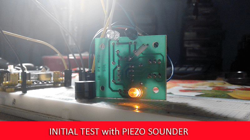
Finally, a quick test video of my piezo-buzzer based prototype (fig 4), sadly without the proposed enclosure. Frankly, I have not yet worked on the actual construction of my enclosure. But when I do get it going I will certainly share!
Smart Cellphone Guard from EFY on Vimeo.
Project file download


