
 The circuit presented here can be used to drive USB-powered smart devices, including smartphones, while riding a bicycle. Smartphones suck battery power extremely fast, particularly when GPS and data connectivity are in constant use, and display and backlight are permanently powered up.
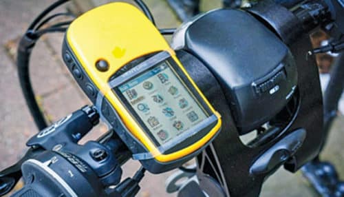
This circuit allows you to power up or recharge the battery of your USB gizmos with the help of solar power. With 9V input from a small polycrystalline solar panel, this circuit produces a regulated output of 5V. The circuit can be used as a standalone 5V USB charger, or a 3.7V lithium-ion battery charger through the support of dedicated electronic components. Fig. 1 shows a typical solar USB bicycle power box.
Circuit and working
The circuit diagram of the solar USB bicycle power box is shown in Fig. 2. It is built around 9V, 450mA solar panel, two 1N5817 Schoktty diodes (D1 and D2), AMS1117 5V fixed-voltage regulator (IC1), TP4056 battery charge controller (IC2) and a few other components.
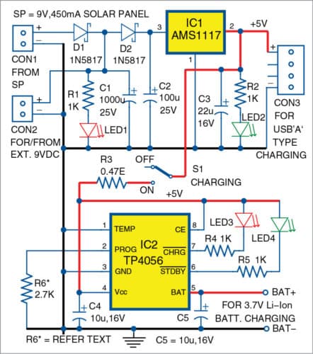
The circuit is self-explanatory. DC voltage (9V@450mA) delivered by the solar panel connected to connector CON1 is routed to the low-drop fixed-voltage regulator AMS1117 (IC1). This input voltage is converted to USB-standard 5V DC supply, and is available through USB socket CON3.
Here, the two 1N5817 Schottky diodes (D1 and D2) are used in the input supply path as their forward voltage drop is only about half that of normal silicon diodes (approximately 0.3V rather than 0.75V per diode at 1A).

The 1000µF buffer capacitor (C1) is charged up to the maximum voltage delivered by the solar panel. For most 9V solar panels, typical maximum output voltage is about 10V.
AMS1117 a 5V fixed-voltage regulator designed to provide up to 1A output current and to operate down to 1V input-to-output differential (dropout voltage of the device is guaranteed 1.3V maximum, decreasing at lower load currents). Note that, CON2 is multipurpose—it can take 9V DC supply catered by the solar panel, or it can feed external 9V DC supply to power the circuit when solar power is not available. Indicators LED1 and LED2 notify about the working status of the circuit.
Rest of the circuit is based on the dedicated lithium-ion TP4056 battery charge controller (IC2). TP4056 is a complete constant-current/constant-voltage linear charger for single-cell lithium-ion batteries. Other features include current monitor, under voltage lockout, automatic recharge, programmable charge current up to 1A, two status pins to indicate charge termination and presence of input voltage, etc.

Two output terminals (BAT+ and BAT-) extended from the lithium-ion charger circuit allow the charging of the 3.7V lithium-ion spare battery. Here, LED3 lights up when the connected battery is being charged, and LED4 notifies the termination of the battery charging process.
Switch S1 can be used to turn on/off the spare battery charger circuitry. Since a 9V, 450mA solar panel is used, charging current is trimmed at 0.4A using a 2.7-kilo-ohm resistor (R6). However, IC1 and IC2 can handle safe currents up to 1A and, hence, it is alright to use a higher-current 9V solar panel as an enhancement. In such a case, change the value of R6 to 1.2-kilo-ohm to set a charging current of 1A.
Construction and testing
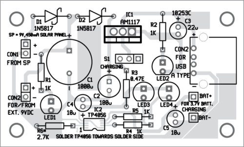
A PCB layout for the solar USB bicycle power box circuit is shown in Fig. 3 and its components layout in Fig. 4. After assembling the circuit on the PCB, connect the 9V solar panel across CON1. (Note that, there are different types of solar panels available in the market that can be suitably mounted on the bicycle for battery charging.)
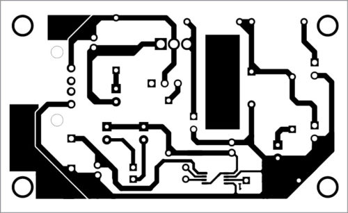
Download PCB and Component Layout PDFs: click here
Since a surface mount device (SMD)-type component is used here, solder both leadless and leaded components to the board. Pay attention to the polarities of the components, study the data sheets closely and ensure that all components are placed with specific orientation on the PCB.
After construction and initial testing, fit the entire circuit in an attractive plastic/acrylic enclosure. Prepare the enclosure with holes for connectors, indicators and switches. Place the finished board in the enclosure. Finally, test again after the board has been fully mounted in the enclosure.
T.K. Hareendran is founder and promoter of TechNode Protolabz


