
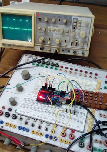
 In this project, the Arduino Uno is configured as a square wave generator with user-selectable control of the frequency and duty cycle. The operating range of the system is up to 10kHz. The desired frequency and duty cycle of the generated square wave can be produced using a matrix keyboard that is interfaced with digital pins of the Arduino. The authors’ prototype of the generator is shown in Fig. 1.
Circuit and working
The circuit diagram of square wave generator built around Arduino Uno board, a matrix keyboard and few other components is shown in Fig. 2.
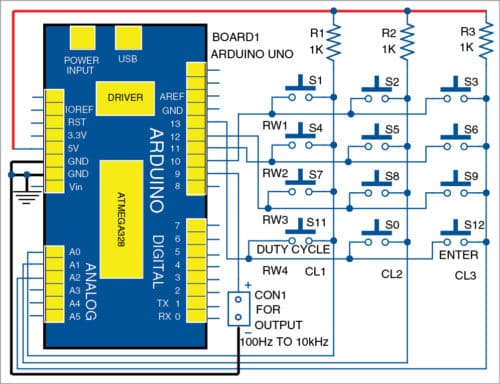
The 4×3 matrix keyboard is used as input device. The four rows (RW1 through RW4) of the keyboard are connected to digital pins 10, 11, 12, and 13 of the Arduino Uno board. The three columns (CL1 through CL3) of the keyboard are connected to the Arduino analogue input pins (A0 through A2). Each column is connected to 5V supply through 1-kilo-ohm resistor (R1 through R3).
Arduino Uno is an AVR ATmega328P microcontroller (MCU) based development board with six analogue input pins and 14 digital I/O pins. The MCU has 32kB ISP flash memory, 2kB RAM and 1kB EEPROM. The board provides serial communication via UART, SPI and I2C.
The MCU can operate at a clock frequency of 16MHz. Here, the digital I/O pins 13, 12, 11, 10 and 9 of the Arduino are configured as output pins. Pins A0, A1, and A2 serve as analogue input pins.

Software
The source code is written in Arduino programming language. The MCU is programmed using Arduino IDE software.
Select the Arduino Uno board from Tools->Board menu in Arduino IDE and upload the wavegenerator.ino code through the standard USB port on your computer. The Serial.begin(9600) function initialises the serial port with a baud rate of 9600. In this project, the serial monitor of Arduino IDE also displays the entered value of frequency and duty cycle for the square wave.

Note. The Arduino must be reset every time a new frequency and duty cycle is required.
The working of the circuit is simple. After uploading the code to Arduino, connect the keyboard as shown in the circuit. Switch on the power and enter the desired value of frequency through the keyboard. Next, press the Duty Cycle button S11 (see Fig. 2) and enter the desired value of the duty cycle by pressing the number keys (S0 through S9). Finally, press the Enter key (S12). The output square waveform is available across CON1, which is connected to digital pin 9 of Arduino Uno.
Download Source Folder
By Shibendu Mahata is MTech (gold medallist) in instrumentation and electronics engineering from Jadavpur University. He has several publications in the domain of signal processing in reputed international journals and conferences.
By Souvik Kumar Das is passionate about electronics and MCU-based system design.


Hi,
Thanks for sharing. Can you share the code file as well? (wavegenartor.ino)
Hi, the source folder is present at the end of the article.