
 Described here is an electronic system for stopping tank overflow. It is capable of keeping the water-level between any two of the eight predetermined levels, starting from the bottom to the top of the water tank.
The technique
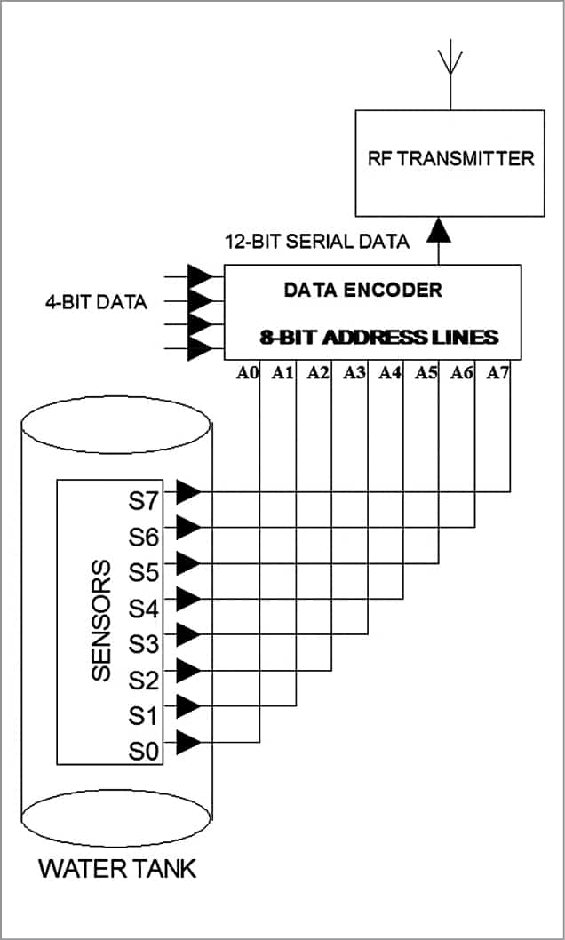
The system uses a point-level controlling technique. Eight different points are chosen along the tank’s height, from bottom to top. Sensors are positioned at each point and wired to address inputs of a special parallel-to-serial (212) digital encoder.
With water level rising or falling, the encoder sequentially follows a well-defined list of numbers (discussed later in the circuit description section). The 8-bit digital number so produced by the sensors is encoded to a serial form by the encoder and is sent to a remote receiving end, wirelessly. Communication between the two ends is done through a pair of 433MHz UHF transmitter and receiver modules, operating in ASK/OOK mode.
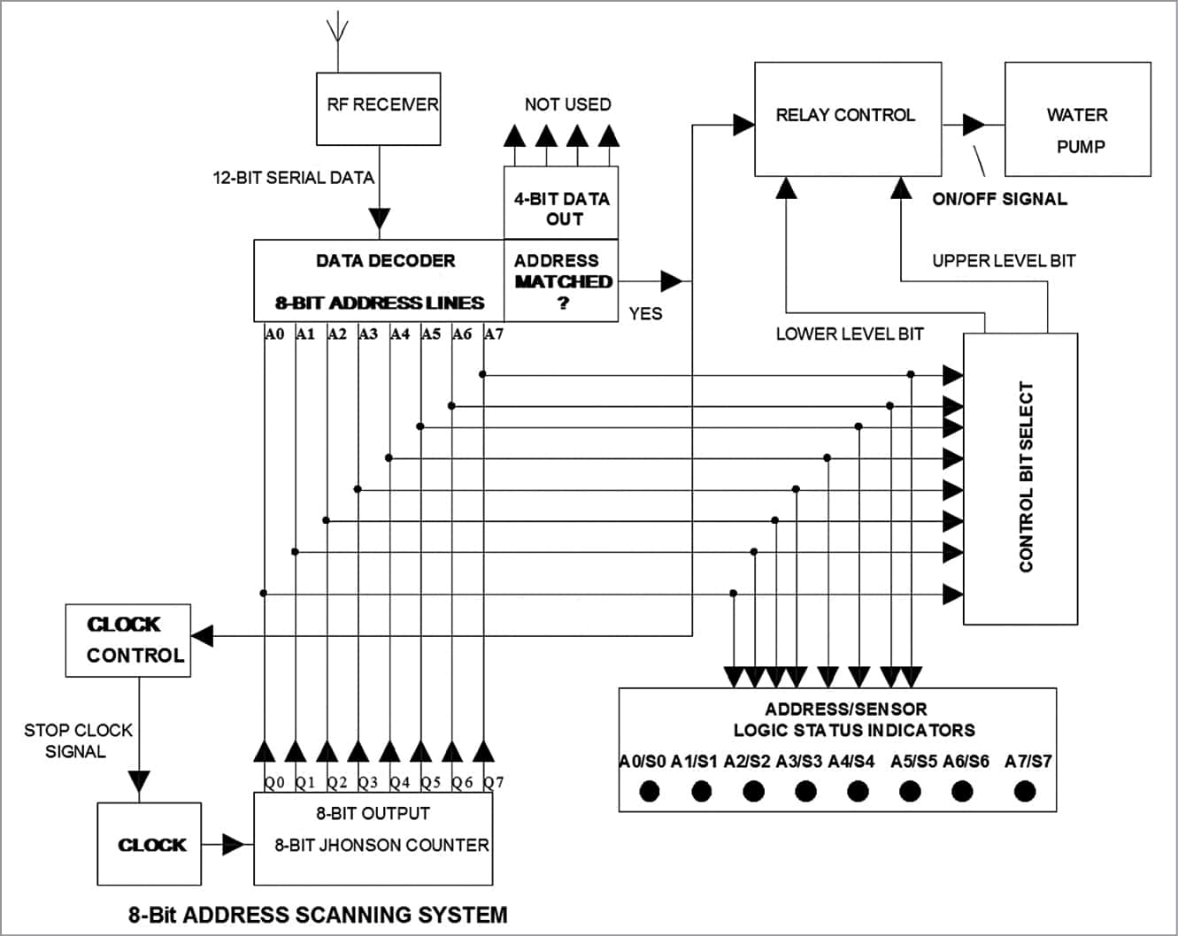
At the receiving end, a compatible serial-to-parallel (212) decoder is used. It decodes and acknowledges transmitted data when, and only when, decoder address lines are fed with matched data. That is, at any time, the digital 8-bit number produced at the encoder by the sensors and the 8-bit number fed to decoder address lines must be the same.
To have a match, a special digital counter continuously generates and feeds sequentially a well-defined list of 8-bit numbers (indicated above) to decoder address lines. As soon as a match is met, the decoder generates a valid transmission (VT) signal. It also outputs 4-bit data sent from the encoder to its data output lines. By using this VT signal, the counter-scanner is stopped, and kept stopped, as long as no new sensor data is generated.

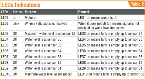
The matched 8-bit number is displayed by eight light-emitting diodes (LEDs). Each LED represents a particular bit of the address lines and, hence, logical status of a particular sensor. If LEDs are marked, a person can easily judge the level of water in the tank by merely observing the status of the said indicator LEDs.
Among the eight digital address bits, any two can be used by a relay-controlling circuit to automatically turn on/off the relay—lower bit to turn relay on and higher bit to turn it off. This, in turn, switches the water pump on/off to keep the water between two levels, represented by said bits.
Block diagrams of the transmitter and receiver are shown in Figs 1 and 2, respectively.

Circuit and working
The circuit for the wireless water level indicator-cum-controller is divided into two units, transmitter and receiver.
Transmitter unit
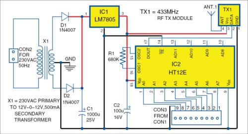
Fig. 3 shows the schematic of the transmitter unit of the wireless water-level controller. It comprises sensor assembly, 5V voltage regulator 7805 (IC1), encoder HT12E (IC2) and 433MHz RF transmitter module (TX1). Transformer X1 converts 230V AC to 12V-0-12V, which is rectified by the diodes (D1 and D2) and regulated by IC1 to provide regulated 5V. Capacitors C1 and C2 are used for filtering. 5V supply enables the circuit.
The sensor assembly holds eight metal strips (S0 through S7) clamped over a plastic pipe (or insulated metal pipe), which is erected vertically from the bottom of the tank. The metal strips act as water-level sensors (Fig. 4). These are generally spaced equally along the length of the pipe from the bottom to full tank height, at 1/8th, 2/8th, etc positions of the pipe length. (These can also be spaced at unequal distances, if desired.) Wires run from these strips to the address lines of the encoder IC. The lowermost one (S0) goes to A0 (pin 1) of the encoder (IC2). The next sensor (S1) goes to A1 (pin 2) and so on, up to S7 that goes to pin 8 of the encoder.

An additional metal strip SG, clamped over the pipe at the bottom of the tank, goes to circuit ground. In case of a metal tank, the tank itself can act as SG. TE input (pin 14) of the encoder is permanently grounded. So, the encoder is configured to produce encoded data continuously. Data is available at its DOUT line (pin 17).
First, connect the sensors from the tank to the circuit and power on the circuit. If water level in the tank stays below S0, no sensor is grounded by conductive water and, hence, digital address input to the encoder is 11111111. If water is pumped into the tank, the level starts rising. When it reaches S0, digital address becomes 11111110. If water level keeps increasing, address lines of encoder HT12E follow digital 8-bit numbers, as tabulated in Table 1.
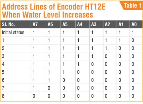
When tank is empty, address line of encoder will be 11111111. When it is full with water-level encoder address will be 0000000.
Hence, at any instant, digital number so produced by the sensors and 4-bit data (if any) at data input lines (pins 10, 11, 12 and 13) of the IC are encoded to serial form by the IC. Encoded serial data, available from pin 17 of HT12E, is steered to data input pin of 433MHz TX module. Module operating in ASK/OOK mode transmits the same to a remote receiving end, wirelessly.
Receiver unit
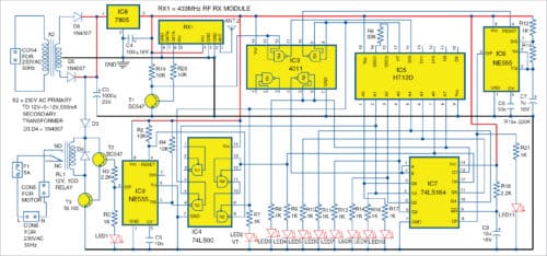
Fig. 5 shows the schematic of the receiving unit of the wireless water level indicator-cum-controller. It is built around transformer X2, 5V voltage regulator 7805 (IC8), NAND gate 4011 (IC3), TTL NAND gate 74LS00 (IC4), decoder HT12D (IC5), two timers NE555 (IC6 and IC9), shift register 74LS164 (IC7), two transistors BC547 (T1 and T2), transistor SL100 (T3), 12V relay and a few discrete components.
Transformer X2 converts 230V AC to 12V-0-12V, which is rectified by the diodes (D5 and D6) and regulated by IC8 to provide regulated 5V. Capacitors C3 and C4 are used for filtering. 5V supply enables the circuit while 12V goes to relay circuit via D3.
RX1, a 433MHz UHF RF receiver module, is used to receive and demodulate the ASK modulated RF signal transmitted by TX1 module of the transmitter unit placed near the overhead tank. Demodulated output is a train of rectangular pulses representing the status (logic levels) of twelve (eight address and four data) bits of the encoder at the transmitting end.
Transistor T1 is used as a pulse amplifier to amplify the signal output from RX1. It raises pulse height to CMOS-compatible logic-1 level (>3.5V at 5V VDD). This compatible output is then fed to pins 12 and 13 of IC3 (internal NAND gate N4). NAND gate helps get pulses of perfect rectangular-wave shape.
Output (pin 11) of NAND gate N4 is fed to input (pin 14) of 212 special decoder IC5. The decoder accepts and decodes the signal from gate N4 when, and only when, logic levels of its 8-bit address match with those of the encoder at the transmitter end. Since address bits of the encoder are not fixed and change with changes in water level in the tank, a special address scanning system is used. The system continuously feeds all possible address bits to the decoder until a match is found.
The address scanning system comprises a Johnson counter constructed around an 8-bit serial-in-parallel-out shift register 74LS164 (IC7). A clock pulse generator NE555 (IC6) feeds the required clock pulse to the shift register continuously. So the counter advances and its outputs follow sequentially the logic levels tabulated in Table 1, first in forward and then in reverse order. IC6 operates in astable mode. Clock pulse rate is governed by resistors R12 and R15, and capacitor C7. LED11 blinks to show the clock’s running status. When power is first turned on, IC7 is reset by power-on reset circuit comprising R18 and C8.
As a result, all output bits of IC7 become logic low. Compliment of the final register output Q7 (which is at logic low now) is fed back as input data to pins 1 and 2 of shift register IC7 through output pin 4 of IC3. So, with clock pulses coming from IC6, the counter advances and its outputs follow sequentially the logic levels tabulated in Table 1, first in forward and then in reverse order. The counter goes on repeating the sequence as long as the clock feeds the counter.
Now, eight outputs of IC7 are tied to eight address lines (A0 through A7) of decoder HT12D. So, at a particular time, when IC7 output matches with the address of the encoder, the decoder is enabled to receive data from pin 11 of IC3, and VT output (pin17) of IC5 goes to logic high. LED2 indicates the reception of a valid signal (VT). This VT signal is complimented by gate N3 of IC3 and is fed to reset pin 4 of clock generator IC6. Hence, as soon as the decoder (IC5) is enabled to receive data, clock reset pin goes to logic low, barring its pulse generation.
The counter stops, as it is not getting any clock pulse from IC6. LED2 remains on, while LED11 goes off to indicate this situation. LEDs connected with the address lines indicate valid addresses at this instant, which is again the status of the sensors at the encoder. Glowing of LEDs (LED3 through LED10) represents logic high, which means the tank is empty (no water), and vice-versa (refer table). For example, status of the LEDs is shown in Table 3.
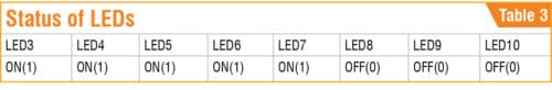
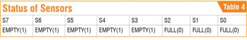
Water level in the corresponding sensor outputs is shown in Table 4.
Level of water in the tank will be above S2, but below S3.
Relay control
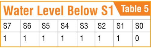
Water level in the tank can be confined between any two predetermined sensor levels. In the circuit diagram, S1 and S6 are chosen for minimum and maximum water levels, respectively. Whenever water level goes below S1, 8-bit sensor output becomes as given in Table 5.
Address scanning at the receiver stops and, consequently, VT goes high when the Johnson counter 74LS164 outputs (Q0 through Q7) becomes as shown in Table 6.

Input pins 4 and 5 of NAND gate N2 of IC4 are tied to VT (pin 17) of IC5 and Q1 (pin 4) of IC7, respectively. As NAND gate N2 of IC4 gets two logic high signals at its pins 4 and 5, its output pin 6 goes to logic low, triggering the bi-stable flip-flop constructed around NE555 (IC9). The IC9 output (pin 3) is set to go high, turning on T2 and T3 (Darlington pair). The relay immediately gets activated and closes the contact. The pump motor is turned on, and stays on as long as the flip-flop is not reset.
Water continues to fill the tank from the level designated by S1. With water level increasing towards the top of the tank, output of the sensors traverses the path, as indicated in Table 1. In doing so, whenever S6 becomes logic low, the corresponding scanned address at the receiver counter 74LS164 output Q6 of IC7 goes low.
Logic state of Q6 of IC7 is inverted by gate N4 of IC4 and its output at pin 11 is fed to input pin 10 of gate N3. The other input gate of N3 is fed with VT (which is at logic high now). Consequently, its output (pin 8) goes high to logic low, resetting the IC9 and, hence, de-energises the relay. The pump stops.
Construction and testing
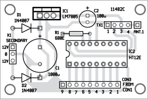
A PCB layout of the Wireless Water-Level Controller and Indicator transmitter unit is shown in Fig. 6 and its components layout in Fig. 7. Assemble the circuit on the PCB and connect 230V AC to the primary of X1.
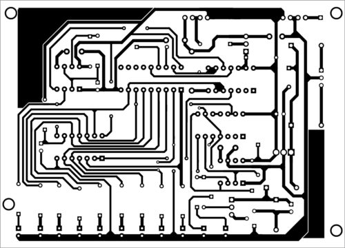
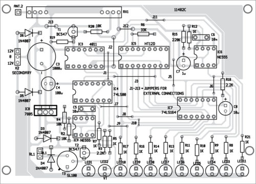
Similarly, an actual-size PCB layout of the Wireless Water-Level Controller and Indicator receiver unit is shown in Fig. 8 and its components layout in Fig. 9. Assemble the circuit on the PCB and connect 230V AC to the primary of X2.

Download PCB and component layout PDFs: click here
Relay RL1 is not connected on the PCB; only relay coil terminals be connected on the PCB. The motor, fuse and AC mains also need to be connected externally.
LED3 through LED10 are used to indicate the water level of the tank. LED3 is for maximum, while LED10 is for minimum-level indications. Glowing of LEDs means the tank is empty.
Assemble two separate units, one for the transmitter and the other for the receiver. To construct the sensor assembly, metal clamps may be used as shown in Fig. 4. These are placed over an insulated aluminium pipe. PVC pipe sleeve is used for insulation. However, the metal pipe can be replaced with a hard plastic pipe, in which case no sleeve is required.
Insulated wires are used to connect the sensors to encoder address lines (A0 to A7) of HT12E. To reduce the length of these wires, the transmitter unit may be mounted in a water-tight plastic box over the tank.
Arup Kumar Sen is ex-technical officer at SAIF Bose Institute, Kolkata


Thank u very much this project i searching long time .Now i fount ok done.
You are most welcome.
is this project based on programming ?
i mean how we transmit the signal from transmitter to receiver ?
do you have instructions for building listening devices?
How to add dry run in this circuit?
I want to use the circuit in reverse manner such that the number of led glowing in the circuit shows emptyness from top I want to make circuit such that numbers of led glowing from bottom shows that tank is full up to that point please give modification and also to include buzzer ckt for tank full connection
Well in that case if you know what are logic gates, I think your problem is already solved because you have to just add one more O/p inverter IC to invert the led state then you will be getting Led on from the empty tank.
for the buzzer add 5v or 9v buzzer along with transistor to drive the buzzer and connect the transistor input to the inverter IC O/P
Nice wireless water level controller design. Thanks EFU
You are welcome UDAI MOHAN YADAV.
Indtad of 8 indicating sensors I want to use 3 but how……let h help me sir…..
Kindly elaborate your query.
how to determine predetermined levels in this Circuit ?
The markings on your tank are predetermined water levels which you can set as per your requirement
I have two questions,
1. we dont need any controller ic here?
2. can you provide gerber file for this circuit? both transmitter and reciever circuits should be placed on a single pcb so that we can seperate them.
how do we run encoder part with batteries for a year at least
is it corrosion free water level circuit ?
No, sensors are not corrosion as these are metal strips.