

This project is based on a capacitive touch sensor for controlling four electrical appliances. Toggle switches have been used for operating lights or fans, and momentary press switches for operating electric doorbells. Most of these switches are mechanical and susceptible to damage through dirt, moisture or mishandling.
Mechanical switches are being replaced by touch switches in some modern homes. Touch switches do not have mechanical wear-and-tear problems and are normally enclosed in suitable boxes, making these resilient in the toughest environments. Some touch switches are designed beautifully, making them aesthetically-pleasing and blend with the room decor. But, commercially-available touch switches are costly. The circuit presented here is low-cost and easy to build.
How the touch switch works
A capacitive sensor works by detecting a change in capacitance due to influence of an external object. The touch plate is covered with insulating material, and the user does not come in contact with the electrical circuit.
A capacitive touch switch has different layers—top insulating face plate followed by touch plate, another insulating layer and then ground plate, as shown in Fig. 1.

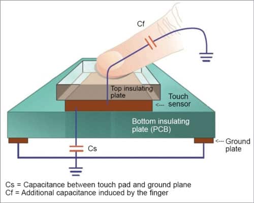
In practice, a capacitive sensor can be made on a double-sided PCB by regarding one side as the touch sensor and the opposite side as ground plate of the capacitor. When power is applied across these plates, the two plates get charged. In equilibrium state, the plates have the same voltage as the power source.
Capacitance is the measure of charge per volt (Cs=Q/V). When a finger is moved near the sensor plate, electric field around the capacitor plate polarises the human body and energy gets transferred to it. This causes more charge to flow to the sensor plate till another equilibrium state is reached. This increases the charge concentration on the sensor plate, causing a change (increase) in capacitance.
It is not necessary to physically touch the sensor plate as disturbance of the electric field near the sensor is enough to induce a change in capacitance. The sensor plate can therefore be placed behind a protective overlay. Induced capacitance is determined by the following relationship:

Cf=kε0(A/d)
where, k is dielectric constant of the protective overlay, ε0 is permittivity of vacuum, A is area of the touch plate and d is separation distance between the conductive plate and the finger.
Dielectric constant of glass ranges between 3.8 and 14.5, while that of plexiglass (acrylic) is between 2.6 and 3.5, of paper is 3.6, and wood has a dielectric constant between 1.4 and 2.9. As such, glass is the best material for the protective overlay, followed by plexiglass.
The touch detector circuit has an oscillator whose frequency is dependent on capacitance of the touchpad. When a finger is moved close to the touchpad, additional capacitance causes frequency of this internal oscillator to change. The detector circuit tracks oscillator frequency at timed intervals, and when the shift crosses the threshold change, the circuit triggers a key-press event.
Touch switch detector
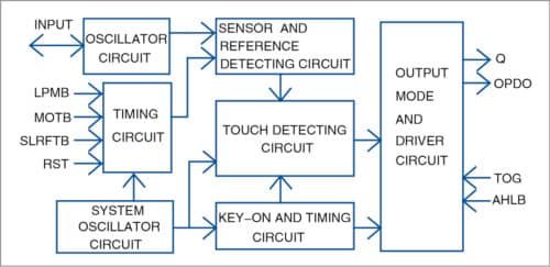
TTP223 is a one-touch keypad detector IC, while TTP224 and TTP225 can manage four and eight pads, respectively. The block diagram of TTP223 IC is shown in Fig. 2.
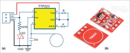
TTP223 IC is available in different packages having sixteen-, eight- or six-pin configurations to suit different applications. In this project, six-pin version is used, and its pin-out is shown in Fig. 3(a).
Behaviour of this package can be altered by making some changes on its pins 4 and 6.
Pin 4(AHLB)
Output is active high when this pin is open, and active low when it is connected to VDD (positive rail).
Pin 6(TOG)
This pin determines the mode of operation. If it is open, output remains in active state as long as the touchpad is touched. If this pin is high(VDD), it operates in toggle mode.
Prebuilt modules built around this single touchpad detector IC TTP223 have been used in this project. These modules are inexpensive and easily available on online portals. The circuit diagram and PCB module are shown in Figs 3(a) and 3(b), respectively.
Circuit and working
For this touch switch panel, four touch switches are used. Three switches function like normal on/off switches, while the fourth works as a momentary switch (bell switch). The number of switches on the panel can be varied depending on requirement.
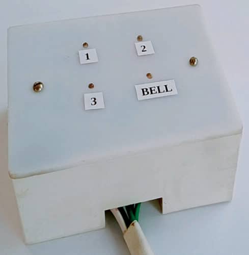
In this project, a suitable-size Bakelite switch box is used to enclose the circuit. Take an acrylic sheet and cut it to the size of the box to make the front touch panel. Various input labels are marked on the acrylic front panel. The author’s prototype of the touch switch panel is shown in Fig. 4.
Before using off-the-shelf touch switch modules, we need to modify them to change their default behaviour. For light switches, two solder pads, marked A and B on the module, have to be shorted. For the bell switch, only pad A is to be shorted, whereas pad B is to be left open. Pad A has to be shorted to match the relays, which have active low inputs.
Further, there is an LED indicator on the module that glows when output is high, as shown in Fig. 3(a). Since this relay module requires an active low signal, indicator LED on the module is always glowing in off state. Remove the indicator LED from each module and instead connect an external 3mm LED, as shown in Fig. 5. Glowing of LED will indicate on state of the appliance on the front panel.
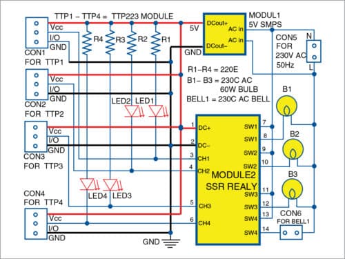
The panel uses four touch switch modules, a four-relay module and a 5V SMPS module to power the circuit. Though any type of relay board can be used, a solid-state relay (SSR) module and a 700mA, 5V SMPS power supply is used here to ensure that all components are easily enclosed in the switch box. TTP223 IC can handle voltages between 2.0V to 5.5V, and power supply should not exceed 5.5V.
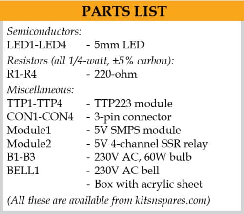
The circuit diagram of the four-channel touch switch panel is shown in Fig. 5. It is built around four inbuilt TTP223 modules (TTP1 through TTP4), 5V SMPS module (Module1), 5V four-channel SSR relay module (Module2), four LEDs (LED1 through LED4), three 230V AC, 60W bulbs (B1 through B3), 230V AC bell (BELL1) and a few other components.
Construction and testing
The relay board and 5V power supply module are suitably placed inside the switch box, as shown in Fig. 6. External lights and the bell are connected to output terminals of the relay board. Touchpads marked as I/O on the modules are connected to input pins of relay modules.
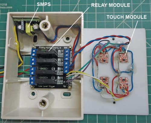
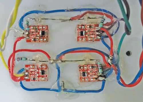
The four modified touch modules along with four LEDs are placed on the acrylic sheet using hot glue, as shown on the right side of Fig. 6. Make four small holes for the LEDs (LED1 through LED4) on the front panel of acrylic sheet. LED1 through LED4 are fixed on the holes using a hot glue gun near the touch modules, such that when a touch module is touched, the corresponding LED glows (Fig. 7). LEDs should be properly placed in the holes so that these are clearly visible on the front panel.
After the connections are made, close the switch box and switch on the power supply. Label the three lights as 1, 2 and 3 on the front panel, as shown in the prototype (Fig. 4). Label BELL as doorbell for the fourth appliance. Now, touch any label, say, 1, on the front panel. LED1 will glow, and the corresponding relay will be energised, which will turn on the first light.
SSR relay module used in this project can handle maximum 2A current, and is suitable for room lights. For switching higher current appliances, replace SSR board with electro-mechanical relays that can handle currents up to 10A.
Ashok Baijal is a regular contributor to EFY, currently retired and working on home automation projects


Good in formation to diy students tq
Thank you for your feedback.
Very useful projects
osm I am using ttp223 in my home automation project thanks for the information