
 XBee Pro (S2) module is an XBee ZB ZigBee Mesh Protocol based wireless transceiver designed by Digi International with an excellent range of 1.6 kilometres (one mile) line of sight (for 50mW, U.FL connection) and 90 metres indoors. This device works on 3.3V DC @ 295mA in transmission mode and has a maximum data rate of 250kbps. The data from the processor to XBee module is transmitted via a serial port.
Raspberry Pi Model 2 is a second-generation Raspberry Pi that was released in February 2015. It is a Linux based computer and has a powerful Broadcom BCM2836 ARMv7 900MHz quad-core processor and 1GB SDRAM. It has a total of 40 pins, including 17 pins GPIO along with HDMI, micro SD card slot, Ethernet, USB 2.0 and 3.5 audio (out) ports.
Software
There are many operating systems designed for Raspberry Pi Model 2, but most widely used are Raspbian (Linux based) and Microsoft Windows 10 IOT Core. If you are a newbie to Raspberry Pi Model 2, check out the link for information on Raspberry Pi. In this article, the compiler used is Python and OS required on Raspberry Pi is Raspbian.
The objective is to send a character on XBee module and receive it on another XBee module. To send/receive data on XBee, the modules should be configured, and to do that the software required is XCTU. XCTU is a free software designed by Digi International that allows a user to configure XBee modules. XCTU can be downloaded from the link
Circuit and working
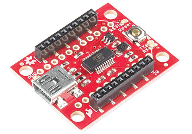
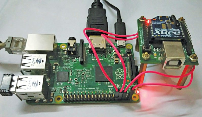
The components required are Raspberry Pi Model 2, two XBee modules with Explorer shields and some female-to-female jumper wires.

To configure XBee module, connect XBee Explorer shield to a computer via USB.
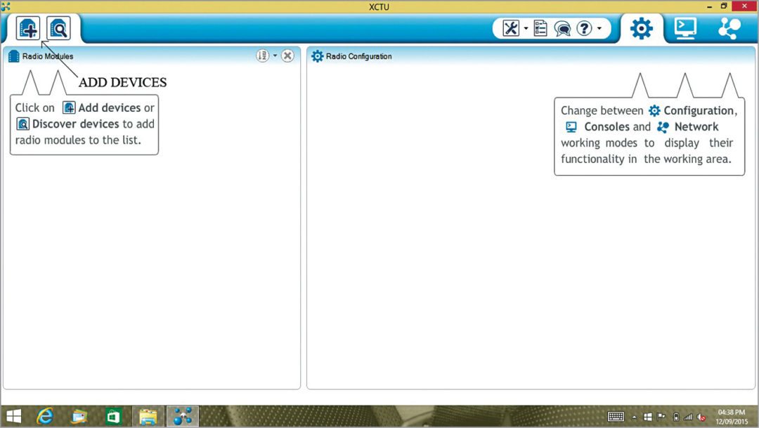
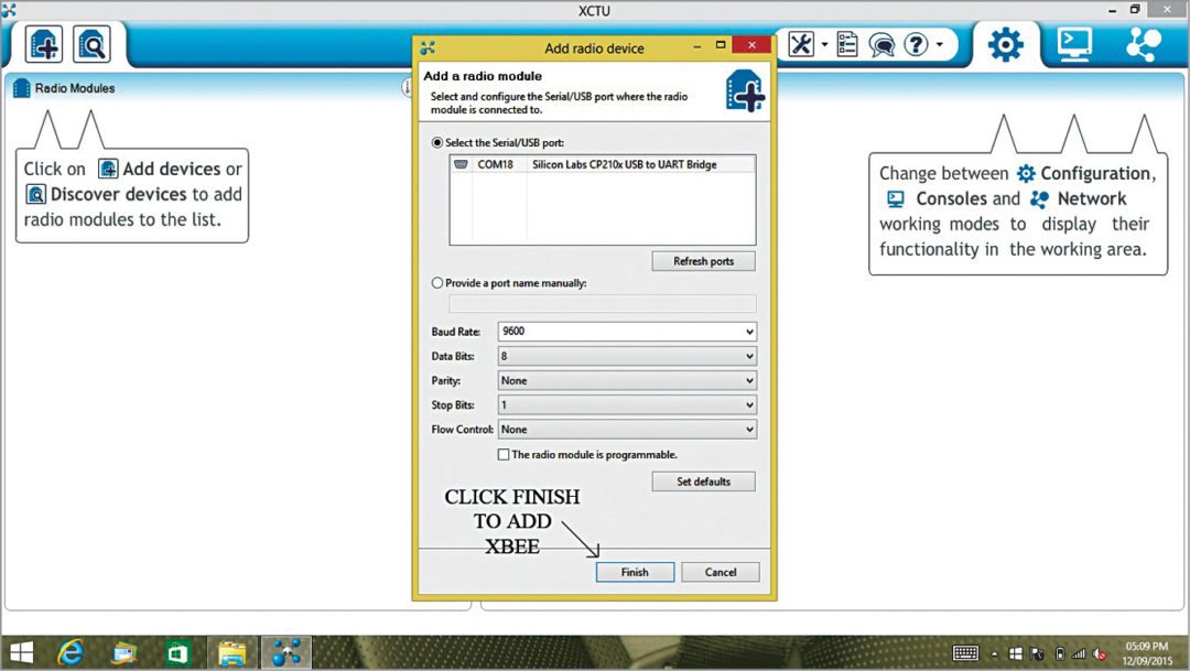
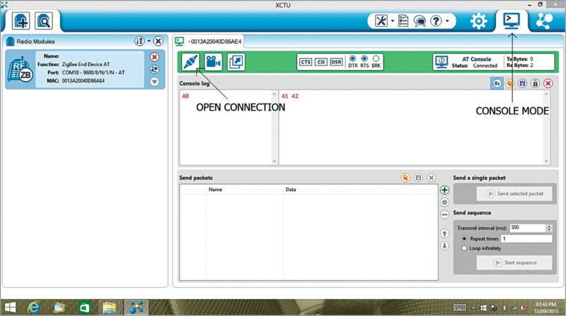
Then run the XCTU software and click on ‘Add Devices’ icon. The output screenshot of XCTU is shown in Fig. 2. You will get an ‘Add radio device’ window. Confirm the COM port of the Explorer and set the baud rate to 9600, data bits to 8, parity to none and click on ‘Finish’ as shown in Fig. 3. Now click on ‘XBee Module’ on the left of the Radio Configuration screen (refer Fig. 5) to configure it. There are three types of devices in a communication network: coordinator, end device and Now first, configure XBee as coordinator.
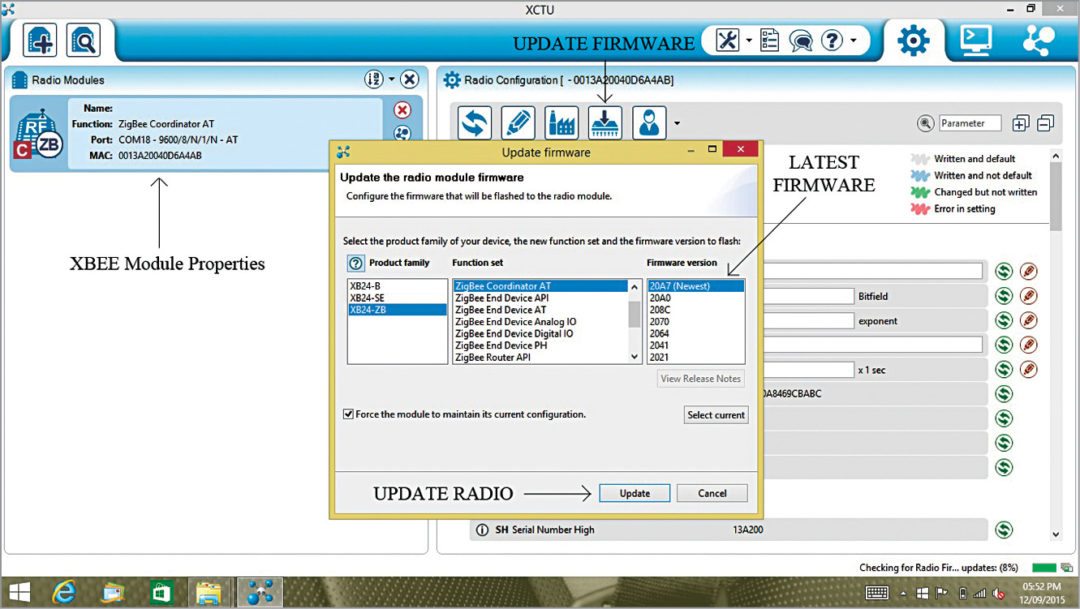
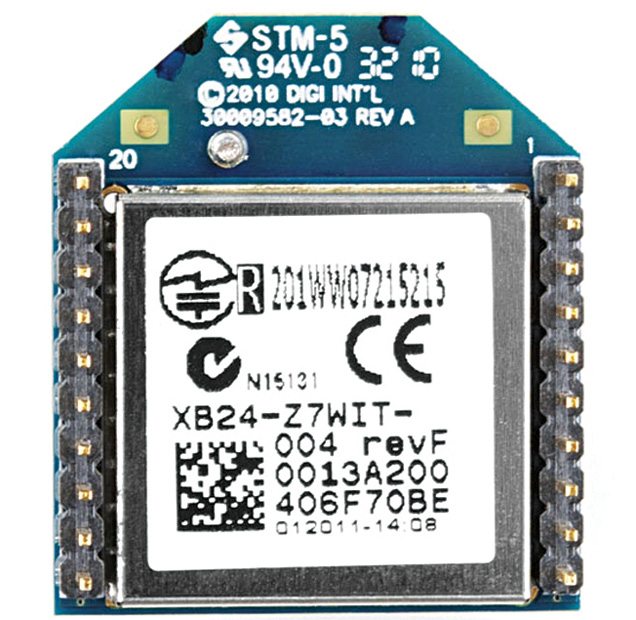
To do that, click on ‘Update Firmware,’ set it to ‘XBee coordinator AT,’ click on the latest firmware available and then click on ‘Finish.’ Each XBee has two important keys, SH and SL, which help in transmission and reception of data. SL is unique to each XBee whereas SH is the same. The bottom view of a typical XBee module is shown in fig 5 along with its SL number as 406F70BEand SH as 0013A200.The coordinator sends the data, so the XBee connected to Raspberry Pi is set as coordinator.

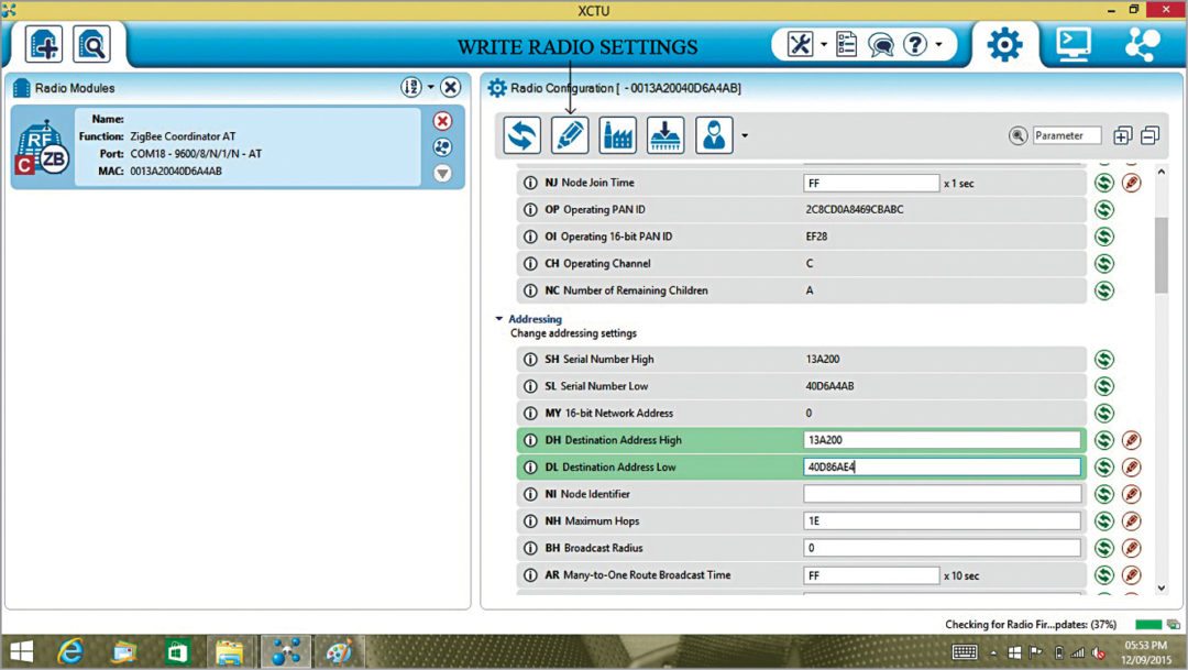
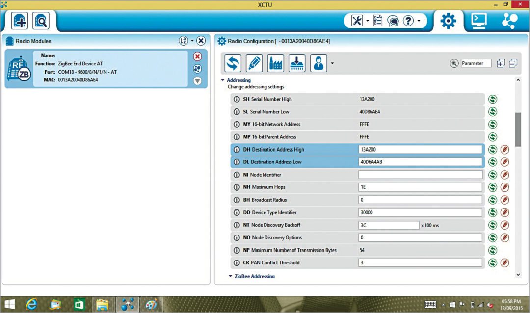
End device receives the data. Here we will use Console Mode of X-CTU to view received data, hence, XBee connected to the computer with XCTU should be set as end device. Router (sort of repeater)is an optional mode; in this, XBee simply receives and then transmits the same data, and so this mode is used to extend the range of transmitter.To configure XB2 as end device, repeat the steps done for configuring XB1, update the firmware and replace its DH and DL values with the SH and SL values of coordinator XB1, respectively. Now XB1 can transmit data and XB2 can receive it. You can see the details of coordinator (XB1) and end device (XB2) modules in Fig. 6 and Fig. 7, respectively.
You can see the details of coordinator (XB1) and end device (XB2) modules in Fig. 6 and Fig. 7, respectively.
XBee Interfacing with Raspberry Pi
The communication between XBee and Raspberry Pi is done through serial communication. The connections for serial communication between XBee and Raspberry Pi Model 2 are given below and also shown in Fig. 8.
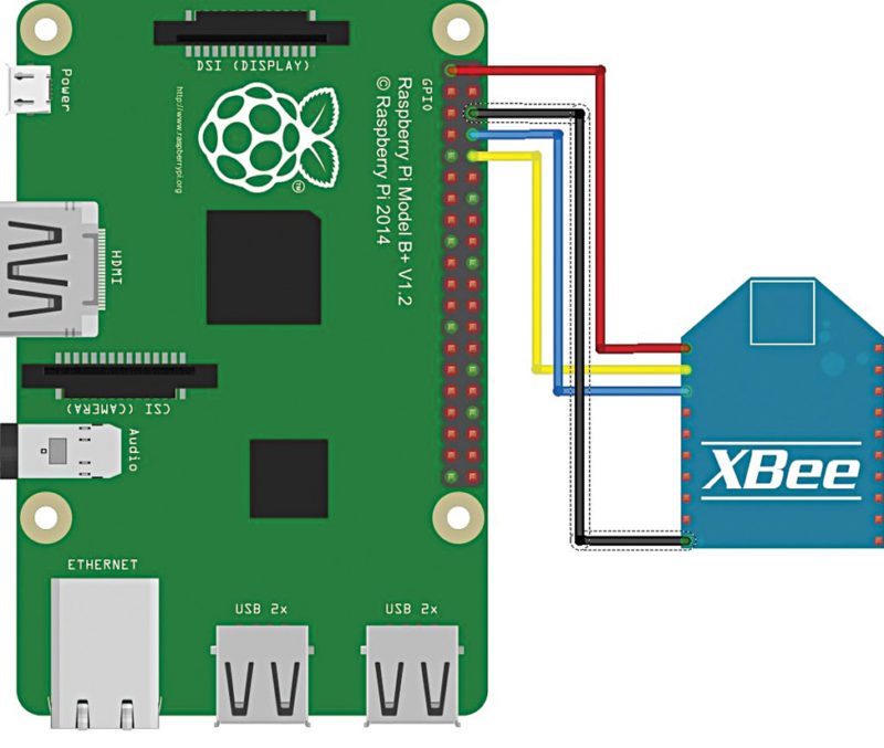
Rx (Pin 3) of XBee ® Pin 08 (GPIO14)
Tx (Pin 2) of XBee ® Pin 10 (GPIO15)
Vcc (Pin 1) of XBee ® Pin 01 (3.3V DC)
GND (Pin 10) of XBee ® Pin 06 (GND)
You need to reboot the Raspberry Pi board after these connections and the configurations as explained below.
In order to use the serial port for communication between Raspberry Pi and XBee, some configurations are required in files cmdline.txt and inittab.txt. Start the ‘Terminal’ on Raspberry Pi board and then follow the given sequence of commands:
[stextbox id=”grey”]pi@raspberrrypi ~ $
sudo apt-get update[/stextbox]
// Checks for updates
[stextbox id=”grey”]pi@raspberrrypi ~ $ sudo apt-get upgrade[/stextbox]
// Installs updates if any
[stextbox id=”grey”]pi@raspberrrypi ~ $ cd /etc[/stextbox]
// This should change directory to etc folder
[stextbox id=”grey”]pi@raspberrypi ~ /etc $ sudo chmod 666
/dev/ttyAMA0[/stextbox]
// To add permission to use serial port
[stextbox id=”grey”]pi@raspberrypi ~ /etc $ sudo apt-get
install python-serial[/stextbox]
// This will install serial Library to Raspberry Pi
[stextbox id=”grey”]pi@raspberrrypi ~ /etc $ cd[/stextbox]
// This should change directory to Root folder
[stextbox id=”grey”]pi@raspberrrypi ~ $ sudo apt-get install
minicom[/stextbox]
// This will install Minicom on your Raspberry Pi
[stextbox id=”grey”]pi@raspberrrypi ~ $ cd /boot[/stextbox]
// This should change directory to Boot folder
[stextbox id=”grey”]pi@raspberrrypi ~ /boot $ sudo cp
cmdline.txt cmdlinebackup.txt[/stextbox]
// This should make a copy of cmdline.txt and rename it to cmdlinebackup.txt
[stextbox id=”grey”]pi@raspberrrypi ~ /boot $ sudo nano
cmdline.txt[/stextbox]
// This should open cmdline.txt in text editor
// Remove: “console=ttyAMA0, 115200 console=ttyl”
// Hit Ctrl+O to Save and Ctrl+X to Exit
[stextbox id=”grey”]pi@raspberrrypi ~ /boot $ cd /etc[/stextbox]
// This should change directory to etc folder
[stextbox id=”grey”]pi@raspberrrypi ~ /etc $ sudo cp inittab
inittab.backup[/stextbox]
// This should make a copy of inittab and rename it to inittab.backup
[stextbox id=”grey”]pi@raspberrrypi ~ /etc $ sudo nano
inittab[/stextbox]
// This should open inittab in text editor
// Comment the line: “T0:23:respawn:/sbin/getty –L ttyAMA0 115200 vt100” // by adding ‘#’ before of it.
// Hit Ctrl+O to Save and Ctrl+X to Exit
[stextbox id=”grey”]pi@raspberrrypi ~ $ sudo minicom –b 9600
–o –D /dev/ttyAMA0[/stextbox]
// This will set the baud rate of the port: ttyAMA0 to 9600
[stextbox id=”grey”]pi@raspberrrypi ~ /etc $ cd[/stextbox]
// This should change directory to main Pi folder
[stextbox id=”grey”]pi@raspberrrypi ~ $ sudo reboot[/stextbox]
// This should restart the system
Now the serial port of Raspberry Pi is disengaged from the boot sequence and can be used to communicate with XBee module. The default baud rate of the ttyAMA0 is 115200, but a baud rate of 9600 is required for XBee. You can change the baud rate in minicom software as given below:
[stextbox id=”grey”]
pi@raspberrrypi ~ $ sudo minicom –b 9600
–o –D /dev/ttyAMA0
[/stextbox]// This will set the baud rate of the port ttyAMA0 to 9600
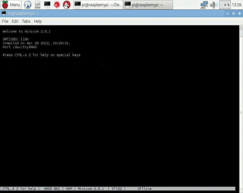
A window, as shown in Fig. 9, will come up. Press Ctrl+A keys followed by Q on the keyboard to exit without resetting.
Python code
Start your Raspberry Pi and create a new ‘XBeeTest’ folder. For this tutorial, the libraries used are ‘serial’ and ‘time.’ Create a new file using nano editor as given below:
[stextbox id=”grey”]
$ pi@raspberrrypi ~ $ cd /XBeeTest
pi@raspberrrypi ~ /XBeeTest$ sudo nano
serial_XBee.py
Here serial_XBee.py is the name of the project. Type the following code:
import serial
// For serial communication
import time
[stextbox id=”grey”]
[/stextbox]
// For delay function
[stextbox id=”grey”]ser = serial.Serial(‘/dev/ttyAMA0’)[/stextbox]
// Set ser as object
[stextbox id=”grey”]ser.baudrate = 9600[/stextbox]
// Set baud rate to 9600
[stextbox id=”grey”]
ser.write(“A”)
[/stextbox]
// Send character ‘A’
[stextbox id=”grey”]time.sleep(1)[/stextbox]
// Give 1 second delay
[stextbox id=”grey”]ser.write(“B”)[/stextbox]
// Send character ‘B’
[stextbox id=”grey”]time.sleep(1)[/stextbox]
// Give 1 second delay
[stextbox id=”grey”]ser.close()[/stextbox]
// Close communication
To save this code, press Ctrl+O keys followed by Ctrl+X.
This code sends character ‘A’ to the console (refer Fig. 10) of the receiver end, pauses for a second and then sends character ‘B.’
Construction and testing
Now it is time to test our project. After saving the code and connecting coordinator mode XBee module to your Raspberry Pi, boot the Raspberry Pi and from the terminal write the following commands to execute your program. The destination folder is XBeeTest and file name is serial_XBee.py
[stextbox id=”grey”]
pi@raspberrrypi ~ $ cd /XBeeTest[/stextbox]
// Change Directory to XBeeTest
[stextbox id=”grey”]
pi@raspberrrypi /XBeeTest
$ sudo python serial_XBee.py
[/stextbox]
// Run serial_XBee.py Program
This program should send character ‘A,’ pause for a second and then send character ‘B.’ Note that, as soon as you power up both the XBee modules, ASSI (Association Indication) LED should light up. In this case, it is a yellow LED as seen in the prototype (Fig. 11).
Now to confirm reception of data, hook up your end device XBee module to your computer, open the console mode in XCTU, start serial communication with XBee module. You should get the output on your screen as shown in Fig. 10.
Download source code
This article was originally published on September 19, 2016 and has been recently updated.
Feel interested? Check out other raspberry pi projects.


Je suis très flatté pour tout ce que vous faites
I followed the exact steps you’ve mentioned. But I didn’t get the result. I’m not able to see anything in XCTU software.
Mail your exact problem on my id: [email protected] and I will try to help you!
No Display on XCTU
Mail your exact problem on my id: [email protected] and I will try to help you!
Hi,
Thanks for sharing your knowledge. While I update the radio module firmware, I only have “ZIGBEE TH Reg”, “805.15.4 TH” and “DIGIMESH 2.4 TH” function set. Is it compulsory to have “XBEE COORDINATOR AT”. Could you please tell me how can I go forward with the available function sets.
hi,
not able to find inittab in /etc folder did the remaining procedure as mentioned but not receiving the data on xctu