
 The circuit presented here is compact and handy for measuring the voltage rating of a Zener diode instantly. To check a Zener diode, it is connected across a DC power supply with a suitable resistor in series, then the voltage drop across Zener diode is measured using a multimeter. The whole setup, including selection of voltage range in multimeter, takes more time than the actual measurement itself.
This circuit uses only a 9V battery as a power supply for checking voltage drop across a Zener diode that may be rated even higher than 9V. It may also be used as a continuity tester, diode junction tester, LED tester, etc. It displays basically the voltage drop across its two probes, which is useful for such testing.
Circuit and working
The circuit diagram of the Zener meter is shown in Fig. 1. It is built around a 5V voltage regulator 7805 (IC1), microcontroller ATtiny85 (IC2), an organic light-emitting diode (OLED) display, transistor 2N2222 (T1), buck-boost converter (Board1) and few other components.
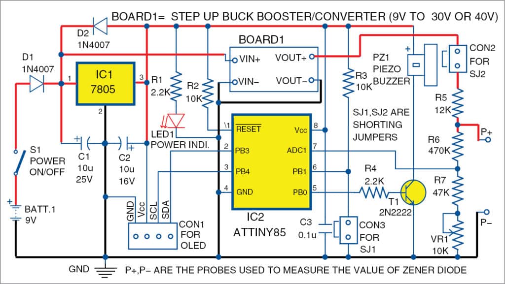
The ATtiny85 microcontroller (MCU) configured as a voltmeter using its ADC channel displays the voltage across the probes on OLED display. A buck-booster module is used to step-up the 9V DC input to about 42V DC, which is required for measuring the voltage drop across the Zener diode. Due to small size of the components used here, the circuit becomes compact and handy.
The OLED display used here is 2.4cm in size with 128×64 pixel resolution, which requires a 5V DC supply and an I2C connector. It has four pins, out of which two are for power supply, one for serial data (SDA) and one for the clock (SCL). The text/message is displayed in 16×8 bit size font and voltage is displayed in 32×24 bit size font.

A buck-boost converter (Board1) is a type of DC-DC switch-mode power supply module to change the output voltage. The buck-boost converter used here is an LM2577 based step-up module. Any step-up buck-boost module with more than 30V DC output may be used in this circuit. The circuit can work in either 0-30V range (in case jumper SJ1 is shorting) or 0-40V range (in case jumper SJ1 is open/disconnected). The range may be selected based on the maximum output of the buck-boost module.
Software
The software code (ZenerMeter.c) for ATtiny85 MCU is written in C language. It requires three libraries (oled_lib.c, font_basic_16x8.h and oled_nums_32x24.h), which are kept in the same folder as ZenerMeter.c. The hex code (ZenerMeter.hex) can be generated using any AVR C compiler such as Programmers Notepad (WinAVR). During testing, we used ISP programmer for burning the hex code ZenerMeter.hex into ATtiny85. You can use any suitable AVR MCU programmer.
The software controls the display through I2C serial communication protocol. The physical I2C pins (SDA and SCL) of ATtiny85 are not used in this project. Note that the OLED can be controlled through two pins of any AVR MCU using software, leaving I2C pins for other applications or control.

A PCB layout for the handy Zener meter is shown in Fig. 2 and its components layout in Fig. 3. Assemble the circuit on the PCB and connect 9V battery to it.
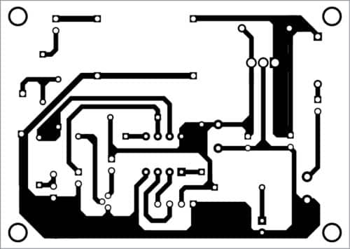
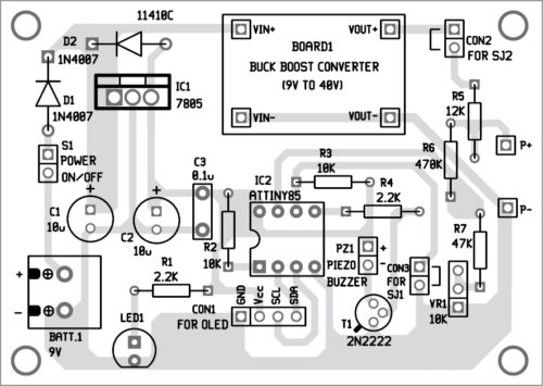
Download PCB and Component Layout PDFs: click here
Download Source Code: click here
Initial setup
- Disconnect shorting jumpers SJ1 and SJ2. Write/program the zenermeter.hex code to ATtiny85 MCU through ISP port using an AVR programmer. Insert the programmed MCU on the PCB. It is recommended to use an 8-pin IC base for the MCU on the PCB.
- Connect a multimeter in voltage mode across Vout+ and Vout- of the buck-boost module (Board1) and switch on S1. Then, adjust inbuilt potmeter of module to get about 42 volts. In case, the maximum output of the module is below 42 volts, then adjust the inbuilt potmeter to about 32 volts. Now, disconnect the multimeter.
- Connect a known voltage source (between 10V DC and 25V DC, say 12V) and a multimeter (in voltage mode) across the probes P+ and P-. Adjust VR1 to match the voltage reading on OLED display with multimeter reading. Now, disconnect the multimeter.
- Connect shorting jumpers SJ1 and SJ2. Now, restart the circuit by switching S1 off and on again. The ‘Zener meter’ along with a maximum voltage range message will appear on the OLED display. Connect the probes (P+ and P-) across a Zener diode, it will start displaying the unknown voltage drop of the diode. The circuit is now ready to use. This circuit can measure Zener voltages of up to 40V.
When no component is connected across the probes (P+ and P-), ‘Zener absent’ message is displayed on the OLED. When a Zener diode is connected (in reverse polarity), the voltage drop across the Zener diode is displayed on the OLED. When a junction diode is connected in forward bias mode, or both the probes are shorted (continuity tester mode), the voltage drop across the probes is displayed and a small beep is generated. In case an LED is connected in forward bias mode, the LED glows and voltage drop across the LED is also displayed.
Fayaz Hassan is a manager at Visakhapatnam Steel Plant, Visakhapatnam, Andhra Pradesh. His interest includes MCU projects, mechatronics, and robotics


