

The market for electric bicycles (e-bikes), particularly those with lithium-ion (Li-ion) batteries, is growing worldwide. When designing power systems for e-bike controllers, it’s important to pay close attention to overall power conversion efficiency and total solution size. This paper discusses ways to implement small, efficient power subsystems for e-bikes.
Introduction: Meeting Power Subsystem Demands for a Growing Market
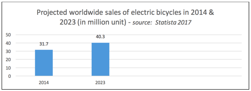
With nearly 35 million unit sales worldwide1, the global e-bike market is huge.
According to Statista, in 2023, global sales of e-bikes are forecast to reach approximately 40 million units.

China has the lion’s share of the e-bike market, but most of these bikes are based on older sealed lead acid (SLA) battery technology. There are two important market trends in the China e-bike market:
- First the China e-bike market is seeing a transition from SLA batteries to new and lighter Li-ion battery chemistry – which requires more complex electronics
- Second, we are seeing higher battery capacity driving higher voltages (up to 54V nominal) to increase the riding range of the e-bikes
Moving to a higher voltage Li-ion chemistry involves developing a control unit which is small and light but still provides enough range to make the bike usable in an urban environment. This means significant system design challenges, especially as it relates to the power subsystem.
System Specifications for E-Bike Controllers
A generic system block diagram of the e-bike controller is shown in Figure 1.
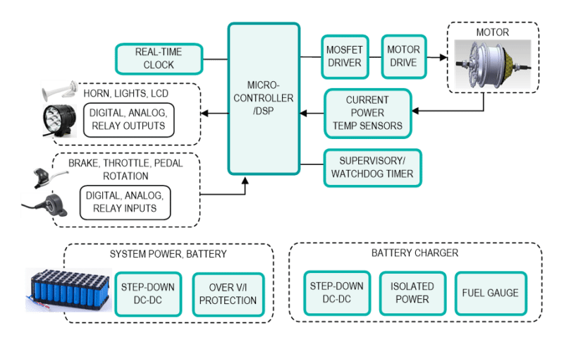
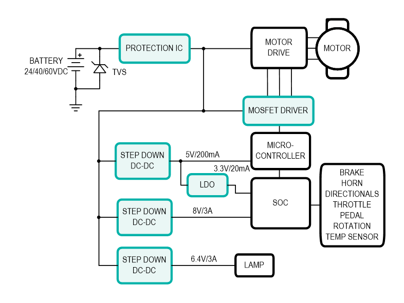
The power for the system comes from the Li-ion battery, which can be 36V and up, depending on the number of battery cells used. This Li-ion battery powers the motor, the MOSFET drivers, the microcontroller as well as other ancillary things like the horn, lights, and hall-effect sensor in the main motor (mostly a brushless DC motor). A generic power architecture is shown in Figure 2.
Existing e-bike controllers are large and bulky; the new controllers are designed to fit within the frame and/or under the seat. This poses two new requirements for the Li-ion battery controller: small solution size and very low heat generation, which is now being dissipated in a much smaller area.
Power Solution Efficiency Impacts Heat Dissipated and E-Bike Range
The range of an e-bike depends on how large the battery pack is, but it is also impacted by the power conversion efficiency of the power subsystem used.
Let’s consider an e-bike with a 36V/10Ah battery pack. The energy in the battery pack is 36V x 10Ah = 360Wh (Watt.Hour). The usable energy in the battery depends on the discharge rate, the ambient temperature, etc. For simplicity, let’s assume all this energy is available to drive the bike. Now, assume the energy used per mile is 14.4Wh (a very typical number for e-bikes). Here is what happens as the power system efficiency goes up:
At 80% efficiency:
Power used for driving the motor = 360Wh x 80% = 288Wh
Range of this e-bike = 288Wh / (14.4Wh/mi) = 20 miles
Power dissipated as heat = 360Wh – 288Wh = 72Wh (or 259kJoules)
At 90% efficiency:
Power used for driving the motor = 360Wh x 90% = 324Wh
Range of this e-bike = 324Wh / (14.4Wh/mi) = 22.5 miles
Power dissipated as heat = 360Wh – 324Wh = 36Wh (or 130kJoules)
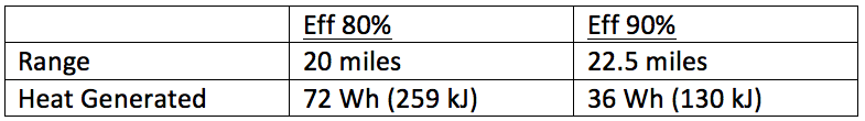
Moving power system efficiency from 80% to 90% can give you a 12.5% increase in range and 50% reduction in heat generation that must be dissipated. Li-ion battery & electronics life degrades with temperature making this a critical decision making criteria.
Table 1 below summarizes the range and heat generated with different power conversion efficiencies.
Let’s consider some of the latest synchronous DC-DC converters in the market, and see how their specifications can enable an optimum power subsystem for an e-bike controller.
Popular Power ICs for e-bike
Let’s go through some power design examples using a couple of popular parts in the market today. Design requirement:
Vin range: 27VDC to 42VDC
Vout: 5V @2A
Tamb: 30oC
Let’s start with Maxim’s MAX17503, a popular 4.5V-60V, 2.5A, high-efficiency, synchronous step-down DC-DC converter. Using the EE-Sim DC-DC Converter tool and choosing a balance design between efficiency and size, the complete power system looks as shown:
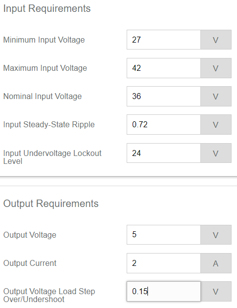
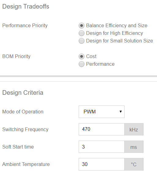
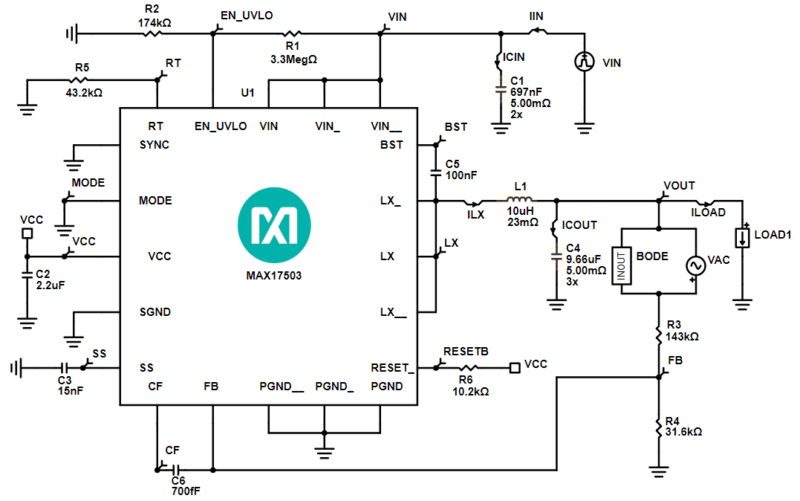
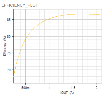
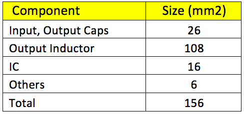
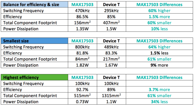
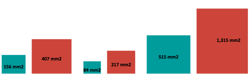
With a relatively small inductor (10uH) this power solution provides an 86.5% power conversion efficiency – Vin = 36V, Vout = 5V @ 2A running at 470kHz switching frequency. The total solution footprint for this power subsystem is 156 mm2, as shown in Table 2 below. The external inductor specifications and the small package of the IC itself help with the ultra-small solution size.
Another DC-DC converter part that has been used in older China e-bikes is a 3.5-V to 60V input, 2.5A step-down converter. Let’s call it Device T, target device for comparison. Using Device T’s online simulation and sizing software, we can estimate size and efficiency of the power system designed with this component. We chose three design options – one design seeking a balance between efficiency and size, another optimized for size and the third focusing on achieving the highest efficiency.
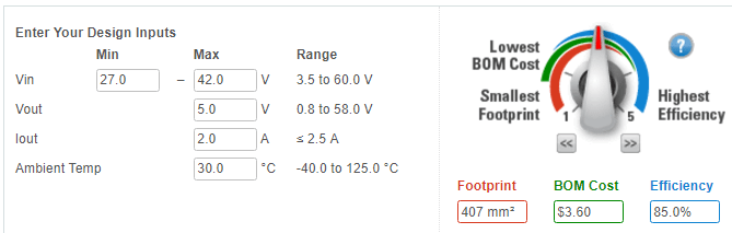
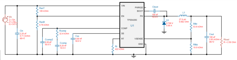
This balanced design runs at 295kHz, yields 85% efficiency, and has a footprint of 407 mm2. This is more than 2.5x the size of the MAX17503 design with a 1.5% lower power conversion efficiency. Note that this Device T design runs at lower switching frequency, thus it requires a larger inductor. The non-synchronous rectification diode also takes some additional space as well.
Let’s redesign this circuit, optimizing for size as follows:
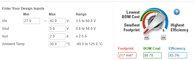
In this compact design, the circuit runs at 489kHz and has a footprint of 217mm2 with even further degradation of efficiency (83.3%).
Redo the design optimized for highest efficiency yields 89%, the converter runs at 100kHz and has a total component footprint of 1315mm2.
For comparison purposes, let’s go back to MAX17503 and create two more designs: one optimized for small size and another for high efficiency.
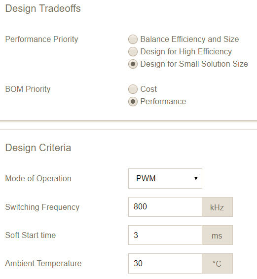
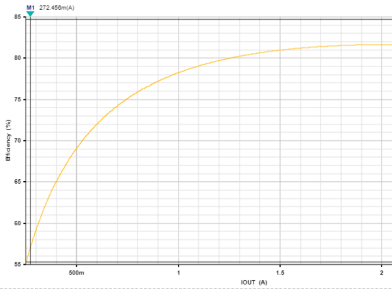
MAX17503 optimized for small solution size:
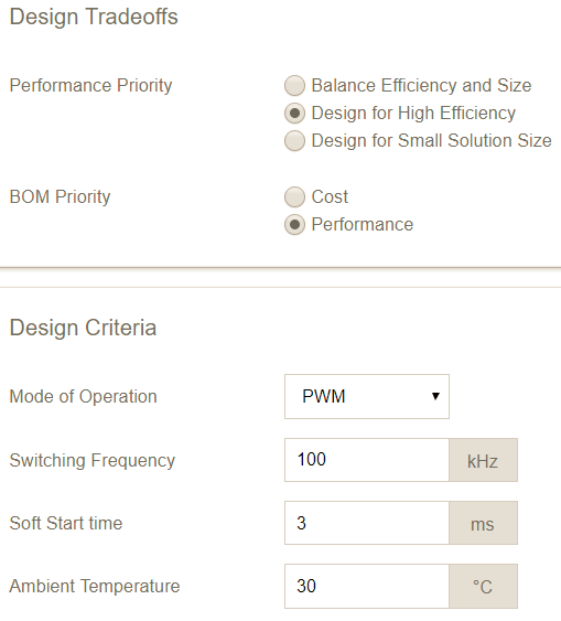
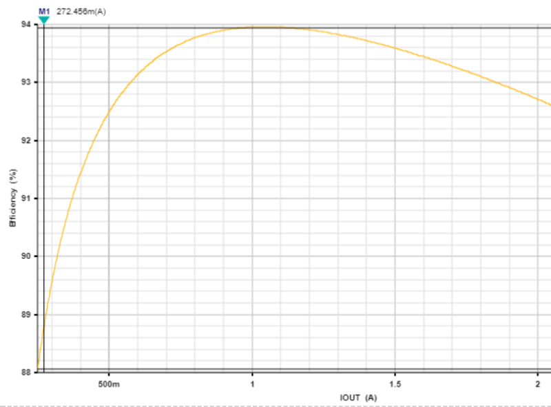
MAX17503 optimized for highest efficiency:
Below is the summary of the design in three distinctive design optimizations:
Vin 27VDC to 42VDC,
Vo = 5V @ 2A,
Ta = 30oC
Power conversion efficiency directly impacts the range of an e-bike. So even a few percentage points difference is crucial. In addition, since this power subsystem needs to fit in a small space (in the tubing or under the seat), the power/heat dissipation must be kept at a minimum to avoid overheating and impact on long-term reliability.
Are a Power IC’s No-Load Quiescent Current and Shutdown Current Important?
There is some confusion on how much a power conversion IC’s quiescent current impacts the driving range since there will be a lot of idle time while using the e-bike in any urban setting. When we run the numbers, we find that even when assuming an excessive amount of idle time the percentage of the battery power that can attributed to the quiescent current of the power IC is virtually negligible.
First, let’s understand how IC manufacturers specify no-load quiescent current:
- Device T specifies it as “Operating non-switching supply current” at 138uA typical
- MAX17503 specifies it as “Input Quiescent Current in PFM mode, IQ_PFM” at a comparable value of 162uA typical
Now, let’s take our same bike with 360Wh battery (20-mile range) down Wangfujing Street in Beijing, where there is one intersection at approximately every 0.2 miles. Assume that we will hit one stop for every two intersections, and that the average wait time is two minutes. During the 20-mile ride, we’d stop 50 times and total idle time would be 100 minutes. With the MAX17503 IQ_PFM of 160uA, the energy consumed during the idle time is merely 0.01Wh, or 0.003% of the total battery energy.
If we took the bike down another street where there are twice as many intersections, we’d consume 0.006% of the total battery energy for the same 20-mile trip. This is still an insignificant amount.
Regarding total shutdown current, the MAX17503 IIN_SH is 4.5uA maximum while Device T’s “shutdown supply current” is at a comparable value of 4uA maximum. At 4.5uA shutdown current, MAX17503 will dissipate 0.12Wh, or 0.032% of the total battery energy after one month in storage. Again, this is not a significant amount.
Real problems customers deal with are heat dissipation and size
Conclusion
E-bikes, especially those designed around the lithium-ion battery chemistry, are a growing market worldwide, especially in China. When the power system for e-bike controllers is designed, system designers must pay close attention to the overall power conversion efficiency and the size of the total solution – including the recommended sizes of the passive components like the inductors and capacitors. The range of an e-bike and the size of the system controller box are directly impacted by these choices made.
References
1 http://www.pedegoelectricbikes.com/wp-content/uploads/2016/07/MF-EBIKE-16-Executive-Summary-w-Pedego.pdf


