An antenna is an electrical device which converts electric power into radio waves, and vice versa.
Antennas are essential components of all equipment that uses radio. They are used in systems such as radio broadcasting, broadcast television, two-way radio, communications receivers, radar, cell phones, and satellite communications. Antennas can be classified in various ways.
Introduction
It is a source or radiator of EM waves, or a sensor of EM waves. It is a transition device or transducer between a guided wave and a free space wave or vice versa. It is an electrical conductor or system of conductors that radiates EM energy into or collects EM energy from free space or it is an impedance matching device, coupling EM waves between Transmission line and free space or vice versa.

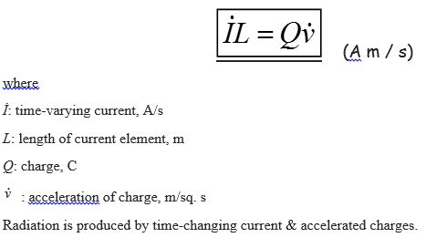
Basic Radiation Equation
Antenna Types
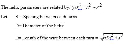
Helical Antenna
Helical Antenna consists of a conducting wire wound in the form of a screw thread forming a helix as shown in figure.In the most cases the helix is used with a ground plane. The helix is usually connected to the center conductor of a co-axial transmission line and the outer conductor of the line is attached to the ground plane.
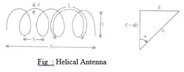
The radiation characteristics of the antenna can be varied by controlling the size of its geometrical properties compared to the wavelength.
Applications
Used in space telemetry application at the ground end of the telemetry link for satellite and space probes at HF and VHF.Low Frequency, Medium Frequency and High Frequency Antennas:
The choice of an antenna for a particular frequency depends on following factors.
- Radiation Efficiency to ensure proper utilization of power.
- Antenna gain and Radiation Pattern
- Knowledge of antenna impendence for efficient matching of the feeder.
- Frequency characteristics and Bandwidth
- Structural consideration
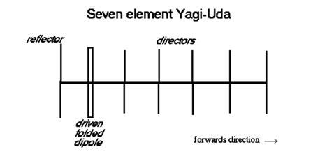
Yagi Uda Antenna
Yagi-Uda or Yagi is named after the inventors Prof. S.Uda and Prof. H.Yagi around 1928.
The basic element used in a Yagi Antennas is λ/2 dipole placed horizontally known as driven element or active element. In order to convert bidirectional dipole into unidirectional system, the passive elements are used which include reflector and director. The passive or parasitic elements are placed parallel to driven element, collinearly placed close together as shown in figure.
The Parasitic element placed in front of driven element is called director whose length is 5% less than the drive element. The element placed at the back of driven element is called reflector whose length is 5% more than that of driver element. The space between the element ranges between 0.1λ to0.3λ.
A Yagi system has the following characteristics:
-
- The three element array (reflector, active and director) is generally referred as “beam antenna”
- It has unidirectional beam of moderate directivity with light weight, low cost and simplicity
- The band width increases between 2% when the space between elements ranges between 0.1λ to 0.15 λ.
- It provides a gain of 8 dB and a front-to-back ratio of 20dB.
- Yagi is also known as super-directive or super gain antenna since the system results a high gain.
- If greater directivity is to be obtained, more directors are used. Array up to 40 elements can be used.
- Arrays can be stacked to increase the directivity.
- Yagi is essentially a fixed frequency device. Frequency sensitivity and bandwidth of about 3% is achievable.
- To increase the directivity Yagi’s can be staked one above the other or one by side of the other.
Corner Reflectors
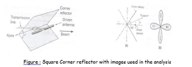
Two flat reflecting sheets intersecting at an angle or corner as in figur form an effective directional antenna. When the corner angle α=900, the sheets intersect at right angles, forming a square- corner reflector. Corner angles both greater or less than 900 can be used although there are practical disadvantages to angles much less than 90. A corner reflector with α=1800 is equivalent to a flat sheet reflector and may be considered as limiting case of the corner reflector.
Assuming perfectly conducting reflecting sheets infinite extent, the method of images can be applied to analyze the corner reflector antenna for angle α = 180°/n, where n is any positive integer. In the analysis of the 90° corner reflector there are 3 image elements, 2, 3 and 4, located shown in Fig. The driven antenna 1the 3 images have currents of equal magnitude. The phase of the currents in I and 4 is same. The phase of the currents in 2 and 3 is the same but 180° out of phase with respect the currents in 1and 4. All elements are assumed to be λ/2 long.
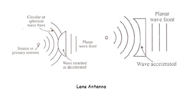
Lens Antenna
Lens is used to convert circular or spherical wave fronts into planar wave fronts, as a transmitter and vice-versa as a receiver. Lens is a medium through which the waves are transmitted or received. Lenses are of two types like decelerating medium and accelerating medium. In decelerating system, the velocity with in the medium is less than that of free space velocity.
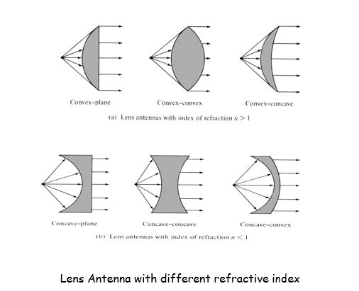
Pure dielectrics like Lucite or polysterene impure dielectrics or H-plane metal plates can be used as decelerating mediums. Accelerating system is the one in which the velocity within the medium is more than that of free space velocity. E-plane metal plates are the examples for accelerating types. Lens Antenna with different refractive index are as shown in figure below.
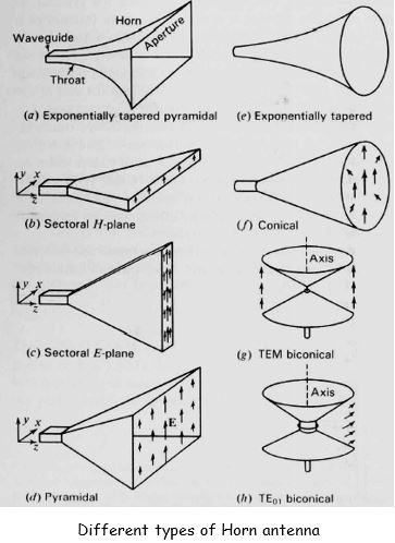
Horn Antennas
Flared waveguides that produce a nearly uniform phase front larger than the waveguide itself. Constructed in a variety of shapes such as sectoral E-plane, sectoral H-plane, pyramidal, conical, etc. as shown in figure.
Horn Antennas – Application Areas
- Used as a feed element for large radio astronomy, satellite tracking and communication dishes
- A common element of phased arrays
- Used in the calibration, other high-gain antennas
- Used for making electromagnetic interference measurements
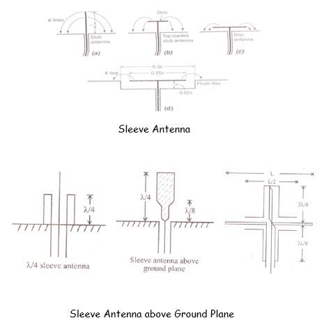
Sleeve Antenna
Ground plane or sleeve type λ/4 long cylindrical system is called a sleeve antenna. The radiation is in a plane normal to the axis of this antenna. The second variety of sleeve is similar to stub with ground plane having the feed point at the centre of the stub. The lower end of the stub is a cylindrical sleeve of length λ/8.
A balanced-sleeve dipole antenna corresponding to the sleeve stub is shown in figure. This is fed with a coaxial cable and balance to unbalance transformer or balun. For L ranging between λ/2 to λ, the operating frequency ranges through 2 to 1. Sleeve antenna above ground plane is as shown in figure
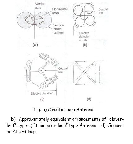
Omni Directional Antennas
Slotted cylinder, and turnstile are almost omni-directional in horizontal plane. Clover-leaf is one more common type of omni-directional whose directivity is much higher than that of turnstile. The system basically contains horizontal dipole which is bidirectional in vertical plane. A circular loop antenna as shown in figure can be used to obtain omni-directional radiation pattern.
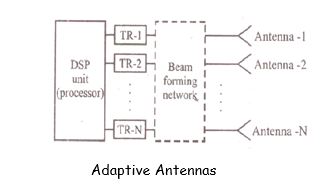
Adaptive Antennas
Adaptive array is the most comprehensive and complex configuration. The system consists of several antennas where each antenna is connected to separate trans-receiver and Digital Signal Processor as shown in figure.
DSP controls the signal level to each element depending upon the requirements. Butler matrix can be adapted for the improvement of SNR during reception. Direction of arrival finding and optimization algorithms are used to select the complex weights for each mobile users. For frequency domain duplexing the transmission weights are estimated based on Direction of arrival information.
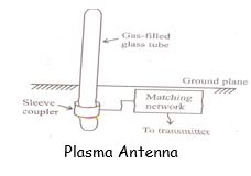
Plasma Antenna
- A plasma surface wave can be excited along a column of low-pressure gas by adequate RF power coupled to the column in a glass tube.
- It is a system in which the radar cross section is only the thin wall glass tube when not transmitting.
- With a laser beam producing the plasma the radar cross section becomes zero when laser is off.
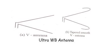
Ultra Wide Band Antenna
- Used for digital Applications
- Pulse Transmission which results in Large bandwidth.
- Phase dispersion of pulse (transmitted at different instant of time)
- Degrading of signals
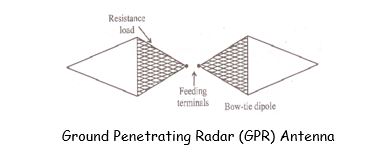
GPR Antennas
- Like Earth Surface Radars, the radars can be used to detect underground anomalies.
- The anomalies include buried metallic or non-metallic objects, earth abnormalities etc.
- Pulse and its echo pulse are used for processing.
- Far field radar equation to be modified as distance travelled by wave is less.
- Power required is more since ground is lossy medium.
- Mismatch at air-ground interface.
- Pulse width should be less.