

An electronic system’s quality test engineer is required to work on different electronic products of different technologies and applications throughout his or her career. This article describes the methodology to be followed by an electronics engineer, when he or she is required to test and certify a new system or product, whose technology and application is unknown to him or her. The methodology is given as a series of steps and can be implemented by anybody.
The methodology for testing a new system or product is almost identical to the methodology followed by people while visiting an unknown city/town. Although Google Maps are extensively used nowadays, earlier people relied on paper maps and common sense. They would get around the city/town using a series of famous landmarks, obtained either through enquiry or paper maps. A similar approach can be adopted here, through a series of steps, involving a top-down methodology of going deep into the system. These steps are explained next.
1. Functionality
No matter how complex an electronics system/product may be, it is designed to perform a specific function or set of functions. The first step in understanding a product is to understand its functionality.

Next comes understanding its application. For example, the product could be a transmitter whose purpose is to modulate information signal on a VHF/UHF/microwave carrier. This product could be used in telecommunications, satellite communications, telemetry measurement systems and so on.
2. Specifications
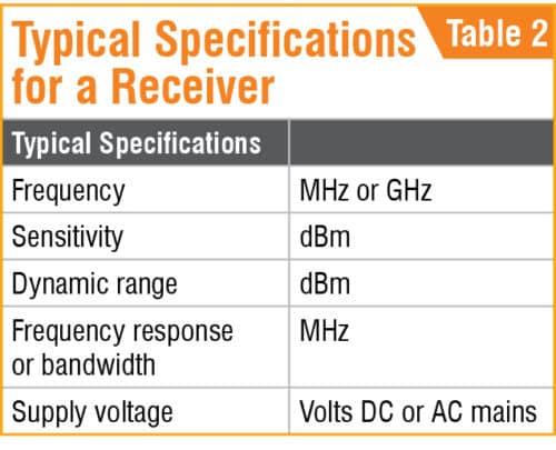
Specifications define how best a product has to perform its function. These also depend on application requirements. Product specifications must be understood by the quality test engineer, since his or her job is to assure that the manufactured product meets all required specifications.
For example, a transmitter will have a frequency specification as per application requirement, its tolerance, modulation index, spurious and harmonics specific performance requirements, and the like. Typical specifications for a transmitter and a receiver are given in Tables 1 and 2, and the lists are not exhaustive.

3. Power and I/Os
All electronic products require power to perform their respective functions. This power could either be DC or mains AC supply. For example, a TV works on mains AC power and a cellphone works on DC power. Hence, the engineer has to understand the power requirements of the product, whether AC or DC, their values and current requirements from the power source.
Every electronic product will have a number of inputs/outputs (I/Os) for interfacing with other systems or the environment. The I/Os must be understood well. These I/Os could be analogue, digital, radio frequency (RF) or power. The engineer should understand every signal, whether it is input or output.
For analogue signals, dynamic range and bandwidth must be known. He or she should also know whether analogue signals are single-ended or differential.
For digital signals, their type (TTL, ECL, etc), standard RS 232, 422 or 485, and so on must be known. The I/Os are distributed on various types of connectors mounted on the unit.
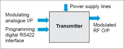
The engineer should know the association between every connector pin and I/Os of the unit. This association is required to arrive at a test setup to test the unit. Some connector pins carry inputs to unit, while some carry outputs. Some are bi-directional, while others may carry power to other units. Typical I/Os for a transmitter unit are given in Fig. 1.
4. Application stress levels
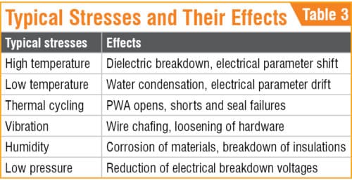
Every product encounters a number of stresses during operation, storage, handling and transportation. Examples of stresses are temperature (high and low), thermal shock, humidity, mechanical shock, vibration and so on. These stresses can cause failure of solder joints, mechanical joints and components by thermal, mechanical and chemical actions. Hence, the test engineer needs to know all these stresses and their values applicable to the product. Typical stresses and their effects on product performance are given in Table 3, and this list is not exhaustive.
5. Regulatory requirements
Local regulatory/standards body requirements of the product must also be adhered to; for example, Pollution Control Body and electromagnetic interference (EMI)/electromagnetic compatibility (EMC). EMI/EMC requirements are important both from regulatory and application points of view.
6. Functional test plan
A functional test plan at ambient conditions has to be arrived at after obtaining all required information. Products are usually tested by applying inputs of appropriate values that occur during application. Analogue inputs can be tested for their entire dynamic range as per design by applying input over the entire range or as per application.
Testing over the entire dynamic range assures good performance of product, even if application requirements change. Expected outputs for inputs should be measured. Digital inputs should be tested by applying levels, patterns and bit rates as per application and logic family/standard of inputs.
RF/microwave receivers should be tested by applying input signal of the appropriate frequency and level with modulation. RF/microwave transmitters must be tested by applying appropriate modulation input. Care should be taken to ensure all I/Os and performance specifications are covered in the test plan.
Some outputs may be DC voltage lines to drive power to other sub-systems. These should not be missed during testing, since their failure can appear later after integration with other sub-systems.
Every product must perform well over a range of supply voltage variations, which are likely to occur during operation and in the installation facility. The test plan should have test cases to ensure that the product performs well over the allowed supply voltage range.
7. Testing for regulatory requirements
After ensuring a functional test plan that the product meets all performance and I/O specifications, alongwith application requirements, the product should be tested to ensure that it meets EMI/EMC and other regulatory requirements. EMI/EMC requirements are important to assure that the product will perform well in the presence of EMI from other electronic systems and that this would not affect performance due to its own electromagnetic emissions.
8. Testing for stress requirements
As indicated earlier, the test plan should have test cases to ensure that the product performs well and meets its functionality and specification requirements under indentified stresses that occur during operation, handling and storage.
Exhaustive testing may not be possible here. Critical parameters must be identified and tested for compliance before, during and after application of stresses for the required duration.
For transportation stresses, operation before and after application of stress should be ensured. Certified environmental test labs and calibrated test instruments should be utilised for this purpose.
9. Testing before delivery
Exhaustive testing as per the functional test plan has to be repeated after completion of stress compliance tests before delivery of the unit. This is because only critical parameters are covered in stress tests, and any other minor failures during stresses will not be known unless exhausting testing is repeated.
10. Documentation
All information collected in the above steps must be converted into a test plan document. This document should have top-level diagrams of the unit showing power and I/Os, description of functionality and working of the unit with a supporting logical block diagram, specifications of functionality, performance, environmental stresses, and regulatory and EMI/EMC requirements.
It should also have a detailed functional test procedure describing how to measure all performance specifications, along with the test setup. Care should be taken to ensure all performance specs and I/Os are covered in the test plan. It should have test results recording formats or test leaves with acceptance criteria to record measured test results in ambient conditions and under various environmental stress conditions.
Finally, it should have a section called conformance report for recording unit information (serial number, model number, project number, etc) and sequence of the tests conducted, any observations/issues in the tests conducted and clearance status of the unit for the intended application.
Conclusion
Tests done as per the document that is prepared and approved as per information under section 10 and test leaves filled as per that document and conformance report for the unit will provide confidence to the management and the customer that the product meets all requirements for the intended application. This is when an electronic quality test engineer’s job is accomplished.
K. Sitarama Rao is working as Scientist G, Reliability and Quality Assurance Directorate (R&QA) of Research Centre Imarat (RCI), DRDO, Hyderabad


