

How does one create an intelligent lighting solution for controlling street lights and lamp posts? What are the subsystems and components that go into it? The folks at STMicroelectronics explain these in detail.
By STMicroelectronics
We have already seen how an intelligent street light solution provides several benefits over traditional systems used widely. We also saw that there are three subsystems in the proposed model of street light control – a Central Monitoring Station (CMS), Data Communication Unit (DCU) and Light Control Unit (LCU). The functions and components of each unit are explained in detail here.
The system – overview
Each street light is equipped with an LCU, the active unit that controls the lamp and communicates with the DCU. The LCU also monitors the lamp status and reports any malfunctioning to the DCU. A mesh network of LCUs is created and each LCU acts as a mesh node. Each mesh has a master unit, that is, DCU. The DCU acts as a root node for the mesh and provides connectivity with the backhaul network. If a particular DCU fails or goes out of the backhaul network, its child nodes can join the adjacent mesh network. Once the failed DCU is corrected and brought online again, the child nodes join it. Now, let us look deeper into each of these subsystems.
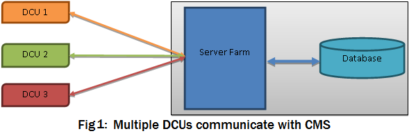

Central Monitoring Station (CMS)
The CMS is typically implemented as a Web application running on a cloud platform. It provides facilities for commissioning, administration and monitoring of each street light node. The network can be organised street-wise. The CMS can store the geographical location, serial number and encryption keys of the DCUs in a database.
The CMS system also provides a remote interface to install new lights and register them in the system. It offers features to update settings of an LCU, such as network affinity, radio channel, parent DCU etc.
In real-time: The CMS collects real-time operational information at the street light level from the DCUs. It presents the information to the user on a dashboard, via a Web interface. The operators can also see a bird’s eye view of the entire system on a map. They can pinpoint any problems in the subsystems using indicators displayed on the map.
Fault alarm: The unit can be configured to raise an alarm when specific conditions arise. It can run diagnostic tests and reports via SMS, email or an audio-visual alarm. It also allows the operator to program ON and OFF schedules in the LCUs, change the light intensity etc.
Communicating to DCUs: A CMS can use multiple techniques to communicate with the DCUs.
- It can use simple Hypertext Transfer Protocol (HTTP) request-based communication. This approach is very simple to implement, but also creates some limitations. HTTP is a connectionless request-response based protocol that introduces some latency in the system. The server has to wait for the client (DCU) to make a request before it can send a command to the DCU.
- The CMS can use protocols like Message Queue Telemetry Transport (MQTT) or Web sockets to have a persistent connection. This method allows for near real-time full-duplex communication. Using these techniques, the server can notify or push a command to the DCU at any time.
- In areas where wireless networks are not available, the CMS can communicate to the DCU using the Unstructured Supplementary Service Data (USSD), in collaboration with network operators.
Data Communication Unit (DCU)
Typically, a single DCU services one or two streets depending upon the number of street lights in the streets. Each DCU has the capability to communicate with 30 to 50 LCUs in a mesh network. To ensure good network performance, care should be taken that the adjacent mesh networks use a different radio channel. Using a low-power radio frequency (RF) transceiver in the sub-GHz band is a good choice for this application. It requires a small number of discrete components, and integrates a configurable baseband modem that supports data management, modulation and demodulation. On the stack side, a low-power wireless personal area network like 6LoWPAN can be used to make a mesh network among multiple LCUs.
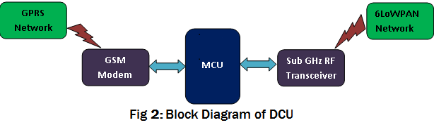
Construction: The DCU is built around a microcontroller that serves as the brain of the unit, and it would have an onboard general packet radio service (GPRS) or a 3G module that communicates with this microcontroller using on-chip universal synchronous/ asynchronous receiver/ transmitter (USART). In case of unavailability of a cellular network, mechanical switches can also be used to switch ON or switch OFF the associated street lights. It also bays on-chip peripherals required for this application, such as a real-time clock (RTC) and serial peripheral interface (SPI). The DCU can also incorporate metering integrated chips (ICs) to measure the power being used by the entire street. Power pilferage can also be detected by adding a metering IC on each street light and then comparing the supplied power with the total power consumed by all the street lights together.


