

The design of a battery charging circuit with or without filter capacitor depends on many factors including the type of battery and the charging method used. One must follow the safety precautions and have basic knowledge about the batteries being charged.
The most common battery charger circuit is the constant-voltage battery charger. It is basically a DC power supply that consists of a step-down transformer to reduce the AC mains voltage and a rectifier to provide the DC voltage to charge the battery.
Some chargers do not deliver pure DC and instead supply a pulsating (uneven) DC voltage. In such cases an output capacitor can be added across the circuit to smoothen the pulses.
In most of the common lead-acid battery charger circuits, capacitors are not required across the output terminals. However, charging a lithium-ion battery is slightly different and requires additional circuitry and a capacitor to protect the battery.
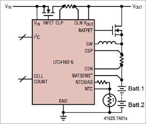
In some designs, a capacitor is used as a bypass capacitor across the output terminals to keep the control loop stable and to keep the ripple voltage low when the battery is disconnected. The use of a bypass capacitor across the output terminals is shown in Figure 2.

There are mainly two types of filter capacitors in battery charging circuits: input filter capacitor and output filter capacitor. The AC voltage across the step-down transformer is rectified and often filtered using capacitors to obtain a regulated DC voltage through a voltage regulator chip to charge the battery.
In most cases, the voltage regulator chip requires input capacitor at its input and also output capacitor at its output terminals. These input and output capacitors are located close to the chip. The input capacitor ensures that the voltage regulator chip connected across the transformer is stable and does not oscillate.
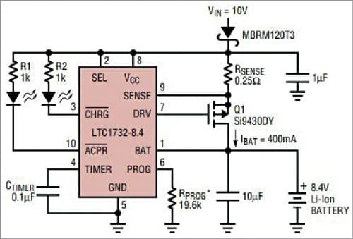
In a simple battery charging circuit, the battery is directly connected across the output capacitor of the voltage regulator chip. In most cases additional filter capacitors are not required in such circuits.


