

Harmonics creates pollution in power system just like carbon dioxide creates air pollution.
Industries are more aware of direct costs related to energy consumption of their machines and processes as it shows up on their every month electricity bill. However, the indirect cost associated due to a loss in energy because of poor power quality, supply voltage quality is also as significant.
The indirect costs are due to the adverse effect of harmonics which includes poor power factor, costly equipment replacements, production losses due to unexpected breakdowns and repairing costs of equipment. Due to these reasons, harmonics have gained attention in various industrial sectors and an increase in awareness of it.
Identification of harmonics and its mitigation can help us to improve process reliability. The equipment availability can be increased due to less downtime costs and also we can have sustainable improvement in power factor.

Fundamental Frequency
The calculation of total harmonic distortion is based on fundamental frequency. Let us understand the fundamental frequency.
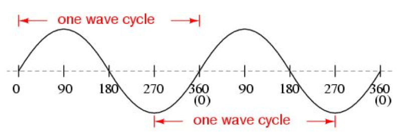
AC generator produces a sinusoidal waveform. The above figure shows AC sinusoidal waveform. The waveform completes one cycle starting from zero up to 360 electrical degrees. If one cycle is completed in one second the waveform is said to have a one-hertz frequency. In India, we have 50 hertz as base frequency, so 50 cycles starting from zero to 360 electrical degree would be completed in one second. USA and Canada have 60 hertz as base frequency, so 60 cycles in a second.
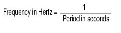
The relation between time and frequency is as below.
Understanding Harmonics Definition
Now let us interpret the definition of harmonics. Harmonics are the components of a distorted waveform and their use allows us to analyze any periodic non-sinusoidal waveform through different sinusoidal waveform components.
Fourier has defined the term harmonics as, “any repetitive waveform can be defined in terms of summing sinusoidal waveforms which are integer multiples (or harmonics) of the fundamental frequency”.
As we can see in figure 1, the waveforms are getting repeated, so the term repetitive waveform has been used in the definition.
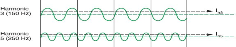
In definition, harmonics are said to be integer multiples of the fundamental frequency. Integer means any ‘n’ number say 1, 3, 5, 7……and so on. Let us consider harmonics current of order 3. ‘Three’ is an integer. This integer would be multiplied with the fundamental frequency. So, the harmonics current of order three would have a frequency of 150 hertz (3 X 50 hertz = 150 hertz). Similarly, if we have harmonics of order 5, 7, and 9 then the harmonic frequency would be of 250 hertz, 350 hertz, and 450 hertz respectively.
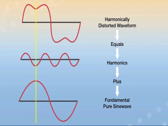
All these harmonics frequencies are summed up together including fundamental frequency or the base frequency and we get total distorted waveform as shown in figure 2.
Understanding Harmonics Definition
We can see the dent in a total waveform which is not sinusoidal. Suppose this distorted waveform is given to any load say motor the current drawn would also not be smooth. The motor may get heated up which may result in permanent damage to it.
There are two types of loads based on the shape of current and voltage waveform. They are:
Linear Loads
A linear element in a power system is a component in which the current is proportional to voltage. This means current waveform shape is same as the voltage as shown in figure 3. Typical examples are motors, capacitors, heaters etc.
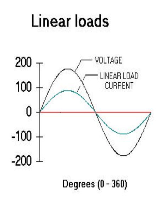
Note that we are talking about the shape of the waveform of current and voltage. In an inductive load, the current lags the voltage by 90 electrical degrees and in capacitive load, the voltage lags the current by 90 electrical degrees, but the shape of waveforms of current and voltage remains the same.
Non-linear loads
When we apply a voltage to solid state device current drawn would be zero until firing voltage reached. As soon as we apply gate pulse, the current is drawn and reached to its peak value. The current drawn would be decreasing, when the voltage waveform goes downwards and it becomes zero till the firing voltage. Same holds true for the negative half cycle. So, the current waveform shape is not sinusoidal but it is periodic as shown in figure 4.
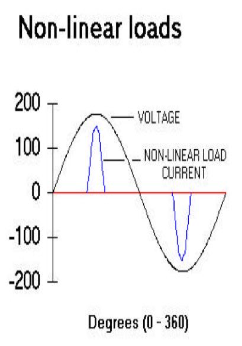
Let us understand in a more elaborate way by taking the example of IGBT. We know that IGBT only gets switched ON when we give gate pulse. If we remove gate pulse the IGBT would be switched OFF even though the power voltage is applied. It will not conduct or draw any current. The IGBT would draw current only when it is switched ON. This is the reason that the current waveform is periodic and hence it is non-linear.
Origin of Harmonics
How are harmonics current generated due to periodic current waveform?
The question arises in mind that due to a periodic current waveform or non-linear current waveform, how harmonics are generated.
We now take IGBT example further. When IGBT is switched ON, it acts as a conductor. When it is switched OFF, it acts as an insulator. So, there is the rate of change of impedance. Due to the rate of change of impedance, the harmonic currents are generated which further distorts voltage waveform of the power system.
Devices producing harmonics
Switch Mode Power Supply (SMPS):
Switch Mode Power Supplies can be found in most of the today’s electronic devices. If input supply is drawn from ac mains, the voltage is first rectified and filtered using a capacitor at the rectified output. The current drawn is periodic which produces a harmonic current of order three or higher. SMPS’s are part of personal computers nowadays. So, harmonics content can also be found in institutes, offices, commercial buildings and even in residential buildings because of its use in electronic home appliances.
Uninterrupted Power Supplies (UPS):
Single phase UPS also produces current harmonics which are widely used in residential buildings and commercial complexes. The voltage from ac mains is first rectified, filtered by the capacitor and then again converted into regulated AC supply. Due to use of rectifier which is normally a full wave bridge rectifier, current drawn from ac mains is periodic and not continuous.
Three phase UPS system have generally 6 pulse bridge rectifiers to convert ac to dc. So, they produce 5th, 7th or even higher order of harmonics.
Variable Frequency Drives (VFD’s):
Variable Frequency Drives are widely used in industries. Variable frequency drives also use bridge rectifiers to convert AC to DC. Due to this, they produce harmonics current of order 6n±1. If we have 6 pulse bridge rectifiers then 5th and 7th order harmonics would be generated. For 12 pulses, 11th and 13 orders of harmonics would be generated. (Cont.)


Neat and precise. Cleared my basics !!
Thank you for your feedback.
Fundamentally strong article… clear my concept, thanks….
Thank you for your feedback.
I must say it is very clear and cleared all the concepts about harmonics
Thank you