

e-Mobility and electric vehicle (EV) charging infrastructure are some of the key focus areas, and relentless research is being done to address high performance in all functional blocks.
With the push to move to electric mobility at a national scale, and with the government being very enthusiastic about deployment of electric vehicles (EVs), the electronics industry can expect to see a lot of activity around indigenous development and manufacturing. While EVs are being worked upon by major OEMs, an ecosystem for development of chargers, charging stations, and software and cloud services is steadily being built. Established companies as well as various startups have started working on these areas, and results are starting to show. However, there is still a lot of opportunity to make the electronics side of it even better.
The government, with the help of BIS, ARAI, EESL and other bodies, has released technical specifications on charging stations. Some of the original specifications like AC-001 and DC-001 have been developed and charging stations have been deployed at select locations. Newer guidelines require charging stations to be equipped with multi-standard chargers, namely, AC type 2, CCS and CHADEMO, in addition to lower power AC and DC-001 ones. However, these systems are reliant entirely on the grid, and are subject to real estate availability at prime urban and semi-urban locations. Besides, the question of the grid being ready and equipped for these added loads still remains.

This is where solar energy and storage comes into the picture, to not only supplement the grid but to also work standalone at feasible locations across the country. Fortunately, India has seen successful solar deployments and enjoys abundance of solar energy due to its geographic location. One-time installation and capital expenses work well for at least 20 to 25 years, with the ROI taken care of in a few years. Energy input thereafter becomes virtually free.
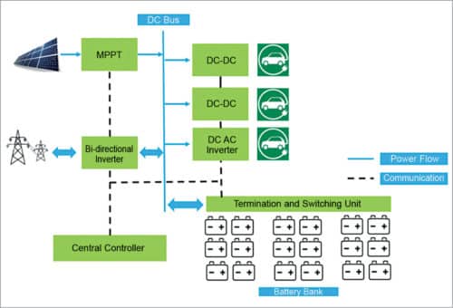
A typical solar EV charging station implementation is shown in Fig. 1. The major building blocks are self-explanatory. There is the user side, which basically depicts functionalities visible to the end user. Information exchange and user interaction is taken care of here. It typically consists of a TFT screen with touch-sensing, NFC card readers for authentication or payments, and maybe a Bluetooth interface for more advanced features.

The vehicle is physically connected to any of the output ports—AC slow charge for smaller vehicles and e-rickshaws, AC fast charge for some classes of vehicles and, of course, DC fast charging. The user has to authenticate himself, set charge preferences and wait till the charge session is over. However, more complex functions go on behind the scene, which are controlled and monitored by the central controller in conjunction with many other modules.
Power flow and energy management
The system has three sources of power. First and foremost are solar panels. Sizing estimation is beyond the scope of this article, but it is typically a few kilowatts at the minimum.
A panel typically produces at rated irradiance about 150W/sqm. Solar panels feed MPPT module. This is a DC-DC converter with a maximum power point tracking algorithm running inside it. These are usually very high efficiency units, running at more than 98 per cent electrical efficiency. These are typically multi-phase interleaved buck or buck-boost converters, whose operating levels are at a few hundred volts at both input and output sides.
Isolation may or may not be a requirement, but most implementations are galvanically-isolated for regulatory and safety reasons. Output feeds a common DC bus, from which downstream energy may be provided to the load. Implementation may be analogue, fully digital, or a mix of analogue and digital control.
The second source is the grid. This may be optional, as the intent is to maximise usage of solar. However, in areas where intermittent grid is available, or where solar insolation is not entirely sufficient for operation year long, or during certain seasons, the grid helps in fulfilling the demand. Since the system is essentially a solar energy storage setup, it is also possible to use this station to supplement the grid during peak hours or as a solar farm, using bi-directional grid-tied inverters. With proper policies in place for exporting to the grid from solar farms or captive plants with net-metering, this serves a dual purpose, too.
The third source or sink/storage is the battery. The trend these days is to use lithium-ion batteries that have a very high cycle life, lend themselves well to quick charging, have very high depth of discharge and very high volumetric efficiency. It is possible to house these batteries underground to save real estate.
Lithium-ion battery packs are arranged in a suitable series parallel combination, and in several strings. The batteries terminate themselves into a junction box and termination unit, which also functions as a supervisor.
Each battery has a data port, typically CAN or RS485, and these are daisy chained and fed to this termination unit, which then has a top-level view of the health and status of every individual battery, string or the entire battery bank. This is essentially a data concentrator and a switching unit, putting battery packs in or out of circuit. In addition, this communicates with the central controller to decide charge and discharge of the batteries.
Fig. 2 makes the power system architecture quite clear. This is a modular system to allow for suitable expansion, and the 3kW to 5kW modules are typically expandable with a communication bus, typically CAN or MODBUS/RS485. The central controller is able to configure the modules as per functional requirement at any point of time—be it charge management, load management or diagnostic checks.
There is a provision within the controller to monitor energy usage, basically kWh consumed, kWh stored and kWh generated/exported. It can also communicate with industry-standard energy meters for billing and tariff setting purposes.
Major power management blocks. The DC-DC converter block is fed from DC bus. Depending on type of vehicle connected and demand raised by the vehicle battery management system for required voltage and current, the central controller configures the DC-DC converter over the communication bus. This option is typically for DC fast charging, and multiple DC-DC converter modules would work in tandem to fulfill the load.
The DC-AC inverter is also fed from DC bus, but this caters to vehicles that can only accept AC to charge or for general slow-charging applications. The bi-directional inverter serves two purposes. It either feeds DC bus to fulfill demand or it exports power back to the grid, when the charging station is lying idle or is needed to supplement the grid during peak hours. Key figures of merit for any power conversion block these days are:
- Very high efficiency: >95 per cent end-to-end are now realistic figures
- Very high power densities: smaller and even smaller systems, as real estate is a significant deployment cost
Both of the above points are met using advancements in silicon. Wide-band-gap semiconductors, especially silicon-carbide devices, are able to work at very high switching frequencies, at much higher junction temperatures and with higher efficiencies. In addition to this, there is an automatic reduction in size of passive components like magnets and capacitors. Better magnetic materials also lend to smaller and low-loss designs, handling much higher powers.
The master central controller is the brain of the station. It performs functions starting from identifying and engaging the user/subscriber till ensuring the vehicle is charged in an optimal manner. It is a powerful combination of high-performance computing, connectivity and sensing. Major functionalities are:
User ID and payment
This is the most visible functionality as far as the user is concerned. This is done through a smart card, OTP, NFC-enabled phones or even Bluetooth. All these sub-systems are controlled by the MPU/MCU on board.
Power management
This is the most critical yet invisible part of the station. The system controller continually monitors the power scenario—supply and demand. Then it decides how to fulfill demand, from supply—whether solar alone is able to supply the load, or a combination of solar and storage is needed, or it needs partial input from the grid as well. There may be scenarios where there could be excess availability or excess demand. It is intelligent enough to route power correspondingly, by altering settings of the various power blocks described earlier.
Connectivity
These days, stations and deployments need to be connected to the cloud for remote monitoring and control. These have to talk to the central management system (CMS) periodically, to report transactions, parametric, diagnostics and operational data. These also need to take operational commands and settings from the CMS. So, a multitude of connectivity options, both wired and wireless, is provided. 3G/4G, Wi-Fi, Ethernet and even LoRa have been used for remote monitoring.
Protections, diagnostics and fault reporting
The system to prevent malfunction has fast-acting protection mechanisms that may be triggered by external events like surges or lightning strikes, or due to operational issues, accidental or deliberate misuse/abuse or from short-circuits, over-temperature or over-voltage/over-current conditions. To keep operational costs low and to have minimum downtime, systems can self-report issues that may arise from time to time. Modular build allows pinpointing which faulty section needs to be replaced at the field, so the technician can arrive well prepared.
A brief explanation of how a solar EV charging system may be deployed is given in this article. It is also possible to customise designs as per needs of the OEM. e-Mobility and EV charging infrastructure are some of the key focus areas, and relentless research is being done to address high performance in all functional blocks. End-to-end silicon for realising realistic EV charging stations is available, along with many reference designs, to keep the time to market short.
Ranajay Mallik works in Systems Research and Applications Systems Application and Integration Lab (SRA-SAIL), STMicroelectronics


