

Previous generations of pilots had only two optical clues to align the aircraft with respect to the carrier and then land safely. The first was called Fresnel Lens Optical Landing System (FLOLS) for vertical positioning of the aircraft. The second was called Centreline Lights for horizontal positioning of the aircraft. But modern-day pilots have an electronic aid called Precision Approach Landing System (PALS).
Precision Approach Landing System
PALS is really a pal for naval pilots. It has three modes: instrumented carrier landing system (ICLS) mode, automatic carrier landing system (ACLS) mode and talk-down mode.
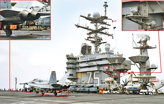
ICLS mode. For an aircraft to land, it has to maintain a constant recommended speed, while losing altitude gradually, until touchdown on the runway. How it loses altitude with respect to the runway is called glideslope. For a runway on ground, the glideslope never changes but since the carrier rocks up and down, the glideslope also varies accordingly and is never constant. So a mere pitch up of the flight deck is drastic for the landing aircraft. Pilot of the aircraft must be made aware of this changing glideslope. This is done through a system called ICLS centred on a radar system called AN/SPN-41.

Though technically not an exact radar system, AN/SPN-41 engages in one-way transmission to the landing aircraft in Ku-band. It has a set of radars: a centreline unit and a flight deck unit. The former is situated beneath the centreline of the runway and the latter is situated slightly high on the flight-deck. Using sector scanning, both units acquire and track the approaching aircraft. The fightdeck unit and centreline unit respectively measure the aircraft’s vertical and horizontal deviation from the glideslope. Then AN/SPN-41 broadcasts the positional difference in pulse mode in Ku-band in real-time.
A system called aircraft approach control system (ACCS) present in the aircraft receives these signals. It extracts the positional information of the aircraft with respect to the glideslope from these signals. It then converts these signals as a set of horizontal and vertical lines on the pilot’s HUD.
The vertical line indicates the position of the aircraft with respect to the centreline of the runway. It appears in the direction that the aircraft has to move so as to align with the centreline of the runway. The horizontal line indicates how much the aircraft must gain or lose altitude to fit in the glideslope.
When these two lines form a crosshair, the aircraft can be perfectly aligned with the glideslope. The pilot, after aligning with the glideslope, can gently nudge his controls to stay in the pitching glideslope until touchdown.
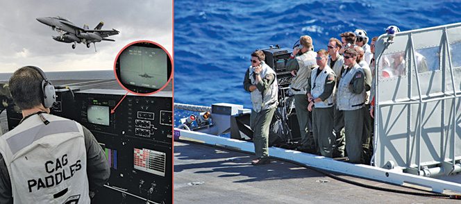
Talk-down mode. In this mode, the pilot is instructed by landing signal officers (LSOs). They work from an LSO console situated at the edge of the flight deck. This console gathers all flight data of the approaching aircraft from many systems. The LSO console computes the required flight path for landing, monitors the flight path of aircraft and the difference that the pilot has to cover. It takes inputs from the integrated launch and recovery television system (ILARTS), AN/SPN-44 radar and wind-measurement system.
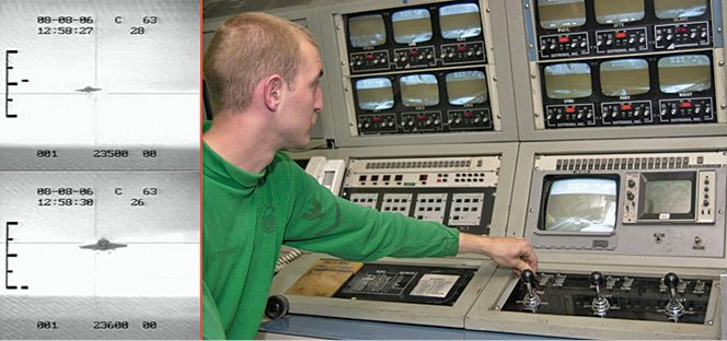
ILARTS. This is a camera-and-television system with all-weather capability. In simple words, its cameras can videograph both during day and night with equal clarity. ILARTS has remotely-operated cameras at many places on the flight-deck. These cameras videograph the approaching aircraft along with its relative position with the horizon. ILARTS then adds glideslope crosshairs parameters and other data to that imagery. The resultant composite video is displayed at the LSO console, CATCC and other important centres like CDC. The aircraft’s alignment with respect to the horizon indicates the LSO whether the aircraft should climb up or descend so as to capture the glideslope of the pitching flight deck.
Fig. 27 indicates the two scenarios of an aircraft approaching for landing. The scale-like symbol on the left indicates acceptable limits for the aircraft in the vertical axis. The dash symbol near this scale indicates the position of the aircraft. The aircraft has to be ideally at the centre of the crosshairs. The dash indicates the actual position of the aircraft with respect to the glideslope. If the aircraft is not within this envelope, it is waved off for another approach. These symbols are generated by ILARTS and fed to the LSO console.
AN/SPN-44. This is known as a range-rate radar. It detects approaching aircraft, tracks it and calculates its speed (both relative to the carrier and true speed). It then provides this data to the LSO console. Supplied with this accurate information on the speed of the approaching aircraft, LSOs can wave off the aircraft attempting to land at an unsafe speed.
Wind-measurement system. This is nothing but a traditional wind-measuring system based on an anemometer. It is used to measure headwind, tailwind and crosswind speeds. These winds can terribly affect the aircraft’s flight by shifting the aircraft. Headwinds resist flight, tailwinds push the aircraft forward and crosswinds laterally move the aircraft out of glideslope. These winds are troublesome. Data from the system is fed to the LSOs, who, in turn, intimate the same to the pilot. The pilot then flies in a way offsetting the effect of these winds.
Based on these inputs, LSOs communicate with the approaching pilot, who constantly adjusts aircraft’s position based on the voice commands given by LSOs.
ACLS mode. Imagine that a pilot is returning to the carrier from a battlefield, which is located 500km away, after bombing enemy targets and evading enemy air defence missiles. On the way back, he or she had to intensely fight with enemy fighter aircraft. Now, on returning to the carrier, the pilot has to land his aircraft under pitch-black conditions. The pilot’s physical state is not as alert as it was when he or she left for the mission; the intense adrenalin rush has tired the pilot, making landing of the aircraft even more difficult. Anyone in this situation would dream of a system that lands the aircraft automatically without any inputs. ACLS is that dream system.
Parts of this system exist in both the carrier and the aircraft. Only ACLS-equipped aircraft can be landed automatically on a carrier. Basically, in an ACLS, autopilot of the aircraft is controlled by the carrier. For this, position of the aircraft is tracked through Ka-band tracking radar AN/SPN-46 in the carrier. Instructions for the autopilot are transmitted to the aircraft. There are two radars guiding each aircraft.
The sequence starts from a point called acquisition window during approach of the aircraft. At this point, the tracking radar acquires the aircraft and starts tracking it. At this point the pilot is indicated through cockpit indicators that the aircraft is being acquired by ACLS. The pilot then puts the aircraft under autopilot in landing mode. The tracking radar uses a conical scan antenna and continuously interrogates a radar beacon present in the aircraft. This beacon responds in X-band for interrogation of the tracking radar. Replies of the beacon are continuously plotted on the ACLS computer to derive the aircraft’s location with respect to the glideslope.
Instructions to the autopilot are transmitted in real-time through a UHF datalink. Autopilot has a component called approach power compensator (APC), which increases or decreases the engine’s power to vary the altitude according to the glideslope requirement. The pilot has warning lights that give indications to abort landing and try for another attempt. Similarly, at any point of time, the pilot can disengage from autopilot by applying pressure on the control stick to take control of the aircraft.
The irony is that pilots do not use this mode! They say that they do not want a computer to land their aircraft. They instead use the instrumented mode and talk-down mode. So this mode only serves as a fallback option during haze and fog.
Mission planning systems
Air operations are planned taking a large number of inputs from various departments and workspaces of the carrier. The following systems help in that planning.
Aviation data management and control system (ADMACS). This is a tactical, real-time LAN used for an aviation-related information-management system. This system helps to manage the aircraft’s launch and recovery operations. This network, extending to aviation-related spaces of the carrier, facilitates strike operation planners with necessary details about aircraft availability and aircraft under maintenance and repair, among others.
Aviation weapons information management systems (AWIMS). This is a data management system to collect, distribute and display information used to manage weapons inventory in a carrier.
Integrated shipboard information system (ISIS). It is a data processing and display system. It integrates all crucial information like tactical, navigational, air operations and meteorological-related data and displays these in a single usable format. To the captain of the ship, entire data regarding the carrier is displayed. Down the hierarchy, only data relevant to a particular function is displayed at various work centres.
In the fifth and concluding part we will discuss command and control operations as well as cruise control operations.


