

Industrial transportation electronics is a broad category. It includes after-market additions for automation and entertainment in cars, trucks, trains, planes, and ships. It also includes infrastructure automation for roads, sea-lanes, trains, and air traffic control to move people and goods more efficiently.
Over the last few decades, after-market automotive products drove remarkable innovation, from infotainment and telematics to ADAS. Examples include GPS, audio, seat back video, rear-view cameras, parking sensors, charging ports, keyless entry, and others. Today, we see all these features integrated into the cars and trucks by OEMs. However, there is a continuous rollout of novel after-market technologies being developed by companies worldwide. Recent innovations include fleet management, on-board diagnostics, heads-up display, gesture-controlled navigation, network gateways, driver assistance, keyless/biometrics-based entry/exit/driving, and freight control/monitoring. These technologies have found places not only in cars and trucks but also in trains, ships, avionics, and defense applications.
Transport infrastructure automation to move people and goods more efficiently includes HOV lane control, parking/toll, fare meters, traffic control, and others. Numerous innovations have made faster movement, on-time schedules, and fewer accidents possible.

In this article, we will discuss the key market trends and customer needs which are presenting new challenges for power supply design for after-market technologies and transport infrastructure automation. Then, we’ll explore solutions to address these challenges, with a special emphasis on power architecture.
Market Trends
One of the most dynamic applications in industrial transportation today is fleet management and logistics. With goods being manufactured and shipped from various regions, states, countries or even overseas, tracking the goods is a big business. For example, when perishables are transported, it is important to ensure they are consistently kept under regulated temperature, pressure, or other parameters. Similarly, secure goods require sensors to track location and entry access. Driver safety is also essential, requiring data from cameras monitoring driver alertness and GPS systems tracking vehicle location. This data is logged using wireless networks and cloud infrastructure, and complex algorithms synthesize the data to make real-time decisions on route and/or driver safety. Several GPS navigation companies have entered the fleet management market, providing hardware and software products and services. North America, Europe, Japan, and Korea each have a long history of advanced fleet management systems. More recently, Latin America, China, and India are adding this capability, presenting a huge growth opportunity. Interestingly, Israel has several players that develop products for consumption in Israel, Africa, Europe, and the rest of the world.
Some might think there is not much innovative technology to add to infotainment, what with so many audio/video, smartphone, and navigation options coming as standard features from OEMs. Yet, trends in this area include integration beyond a simple smartphone interface to add heads-up display (HUD) that projects the phone screen onto the windshield glass with gesture control to navigate between maps and video calls, or other salient features like weather, stock ticker, calendar, etc. Seat back screens to mirror the phone screen for rear passengers is also an active product development area.
Advanced driver assistance systems (ADAS) is a growing market today. After-market ADAS includes parking sensors, rear-/extended-view cameras, lighting, traffic warnings, car-to-car (vehicle-to-vehicle) interface, and others. Several manufacturers are working on solutions that enable drivers to avoid unintended lane departures, collisions, pedestrians, and road hazards, as well as drive within the speed limit.
With the amount of time people spend in cars in highly congested urban cities, many cars and buses are also adding wireless gateways. This enables passengers to continue to work during long commutes between home and office/school.
Typical System Architecture
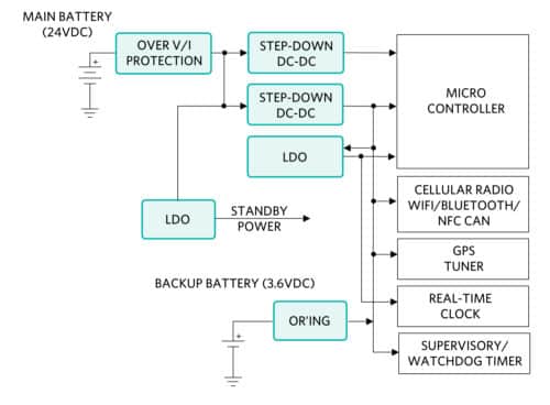
Here is a typical fleet tracking/management system architecture:

Power Architecture
The fleet tracking/management device is powered by the vehicle battery, typically 12V in cars and 24V in many trucks. As an after-market add-on, it faces a much harsher power management environment than a well-bounded OEM device. Most devices also have a rechargeable backup battery, typically 3.6V, intended to last two or three days when the main battery power is lost. From the main battery source, the front-end electronics are protected against transient and fault conditions. The protected voltage is converted to useable, lower voltages (3.3V, 2.5V, 1.2V, etc.) by step-down DC-DC converters and LDOs to power various digital logic and analog ICs.
Protecting the Device from Faults
Like many other electronics that draw power from a vehicle battery, the fleet tracking/management device must be protected from voltage surges commonly known such as load dump, regenerative braking, long cable ringing, etc. Load dump is an event where the battery cable is suddenly disconnected while the alternator is spinning, putting high energy back to the vehicle power cable where there is nothing to absorb it, causing high voltages that could destroy unprotected electronics. Regenerative braking occurs in an electric vehicle when the driver applies the brake; the vehicle kinetic energy is captured by the motor and sent back to charge the battery. Due to the high energy, high di/dt nature of regenerative braking, there will be high voltage ringing associated with this event.Long cable ringing occurs when there is a high di/dt event such as plugging in a device to an on-board diagnostic connector. The surge current charging the device’s on-board capacitors or backup battery will resonate with the cable’s inductance, causing high voltage ringing. Longer cables, with higher parasitic inductance, will exhibit more severe voltage ringing. The new OBD-II standard dictates that the diagnostic connector be within two feet (0.61m) of the steering wheel while the main battery is far away under the hood or on a side of a truck. This new requirement makes the cable from the battery to the OBD-II connector longer and more prone to high voltage ringing.
Cable Ringing Causes High Voltage Faults
Figure 3 shows a lab setup to demonstrate cable ringing. A 24VDC power source is used to emulate a 24VDC battery from a truck. A 10-foot cable connects the power source to a ceramic capacitor (either 1uF or 10uF) to emulate an input capacitance of a fleet tracking device.

Figure 4 shows our first test, emulating cable ringing at initial plug-in when the in-rush current charging the capacitor (previously discharged) built up through the cable parasitic inductance resonates with the board input capacitance. With 10uF input capacitance, the peak ringing voltage is 32V with a voltage spike at 42.6V. With 1uF input capacitance, the peak ringing voltage is at 40V.
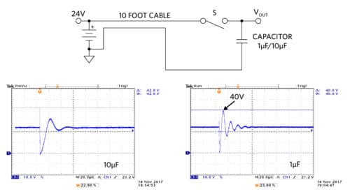
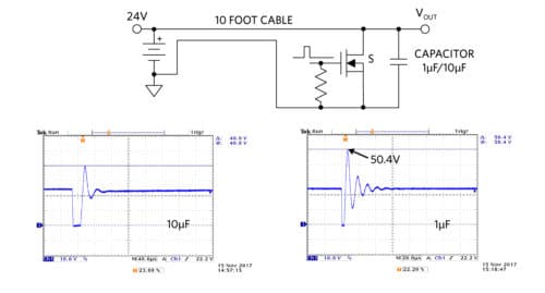
Figure 5 shows our second test, where we emulate a brief short-circuit condition across the cable. Once the short is removed, the short-circuit current built up through the cable parasitic inductance resonates with the board input capacitance. With 10uF input capacitance, the peak ringing voltage is 40V. With 1uF input capacitance, the peak ringing voltage is at 50.4V, more than doubling the source voltage of 24V.
We use 10 feet of cable in this experiment, which is a reasonable estimation of the truck cable length from its battery to an OBD-II connector just to demonstrate that the peak ringing voltage can easily double the input voltage source. The high peak ringing voltage can occur at different cable lengths and at different device input capacitance. In fact, peak ringing voltage can be calculated as:
Vpk=Ipk√(L/C)
Where Ipk is the peak short circuit current and √(L/C) is the characteristic impedance of the system. L in this case is the cable parasitic inductance and C is the device input capacitance.
Other Faults
Electronic components can encounter short-circuit faults. Short-circuit and/or overcurrent protection circuitry is essential for preventing fire hazards as well as isolating the power cable from a failed short device.
When the ambient temperature become excessive or if there is some other fault (overcurrent, etc.), the over-temperature protection prevents permanent damage by either scaling down the power dissipation or shutting down the device completely. Over-temperature protection prevents system overheating and fire hazards, and ensures that the system operates within its defined temperature limits.
Reverse voltage fault occurs when the battery is connected in reverse or the power cable is installed backwards. While unlikely to happen, reverse voltage fault usually produces expensive damage to the power cables and electronic devices connected to the cable without proper reverse voltage protection.
We’ve discussed the need to protect the device from many possible faults. Implementing fault protection circuits with discrete components can be quite tedious, expensive, and not fool-proof. The solution is large due to the high number of components. The system designer faces the challenge to verify and guarantee the circuit performance over time. Total cost of ownership is high due to system inflexibility when responding to a fault (open a switch, shut down the system, which requires a technician to restart).
Figure 6 illustrates a modern protection IC from Maxim’s Olympus family of devices, MAX17523 – 36V/1A. This highly integrated IC packs all needed protections into a single, tiny 16-pin TQFN 3x3mm package. This device is very simple to use while providing a rugged solution to the 12V transportation electronics. Some of the MAX17523 features are:
- High input voltage tolerance (+4.5V to +36V operating range)
- Reverse voltage protection (tolerates -36V negative input voltage)
- Reverse current protection
- Short circuit, over current protection
- Over temperature protection
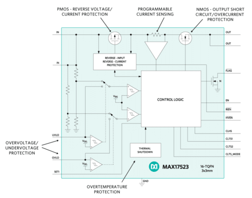
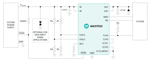
Fig. 6: MAX17523 typical application schematic
For 24V transportation systems, a higher voltage rating protection IC is needed. The MAX17525 – Maxim’s Olympus Protection IC +5.5V to +60V, 0.6A to 6A is perfect for the job. The device is in a space saving 20-TQFN 5x5mm. Some of the MAX17525 features are:
- High input voltage tolerance (+5.5V to +60V operating range)
- Reverse voltage/current protection (tolerates -60V negative input voltage)
- Short-circuit, thermal foldback current-limit protection
- Over temperature protection
- Adjustable OVLO, UVLO, startup current, and forward current limit
Powering the Device with Modern DC-DC Regulators
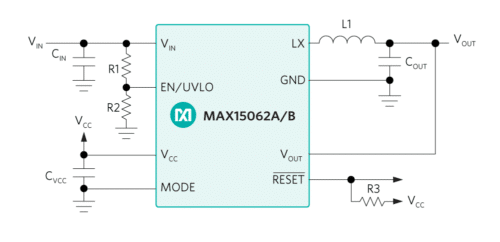
The fleet tracking/management device, like other transportation electronics, is physically small. Removing the heat dissipation from the device to keep its temperature within range is a challenge. Fitting the power circuit into a small space requires high integration. Modern DC-DC power solutions that effectively integrate the power MOSFETs, compensation circuit, and other external components help reduce the circuit size. Combining the small solution size with the efficient synchronous rectification technology helps reduce the power dissipation. MAX15062 (4.5V-60V, 300mA), from Maxim’s Himalaya family, is an example of such a device, providing 92% peak efficiency in a tiny 8-TDFN 2x2mm package.
To further increase integration, Himalaya power modules also integrate the power inductor, resistors, and capacitors with a DC-DC regulator. The result is easy-to-use, easy-to-design, and quick time-to-market power module solutions that only require an input capacitor, an output capacitor, two small voltage setting resistors, and an optional soft-start setting capacitor to complete the power solution. MAXM17545 (4.5V to 42V, 1.7A) and MAXM17575 (4.5V to 60V, 1.5A) are good examples of Himalaya power modules.
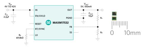
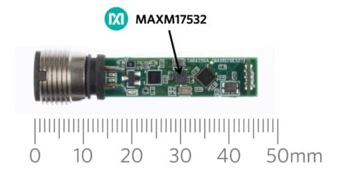
Today’s automobiles have hundreds of sensors. The same situation is true in intelligent transport automation. In both of these cases, the sensors are being added to equipment with extreme space constraints. Powering sensors requires even higher integration. MAXM17532 uses revolutionary packaging technology to miniaturize a 42V, 100mA power solution into a 2.6x3x1.5mm power module. This highly efficient synchronous DC-DC buck power module also minimizes the heat dissipation in the sensor.
- 4.0V to 42V VIN range
- 0.9 – 5.5V VOUT range
- 100mA continuous current
One might say: I can power the sensor using an LDO! Yes, this is true since LDO is generally low cost and very simple to use, but it has high power dissipation, which is a main drawback. For example, a traditional simple digital/analog sensor might need 5V at 20mA and has 24V input (nominal). The power dissipation across the LDO is (24V – 5V) x 20mA = 0.38W (nominal). Newer sensors are packed with more intelligence, more functionality, and more flexibility – all of which also require more power, say 100mA.
Keeping the same input/output voltages, the power dissipation across the LDO would be (24V – 5V) x 100mA = 1.9W. This significantly higher power dissipation must be dissipated in the same sensor’s physical form factor. On top of this, there are now a lot more circuitries added to the sensor, requiring smaller size and higher integration. A power module that can address size and power dissipation requirements while delivering great efficiency would fit the bill here. Low power dissipation means lower system operating temperature and higher long-term reliability.
Summary
The after-market transportation electronics industry is growing to address both in-vehicle systems and transport infrastructure. Equipment designed for this market must be robust against transient conditions such as over voltage, over current, reverse voltage, reverse current, over temperature, etc. Highly integrated protection ICs provide all of the above protections and simplify the design over discrete solutions. Equipment is getting more functionality yet shrinking in size, requiring higher integration. Highly efficient power management solutions mitigate thermal dissipation challenges and enhance long-term reliability of the system.


