

Underwater laser communication is a technique that employs laser propagation under water to transmit data from one point to another. The technology is useful where physical connections through fibre optic cables are impractical due to high costs or other considerations.
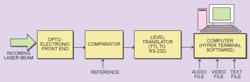
Free Space Optics (FSO) technology is based on connectivity between FSO-based optical wireless terminals, each consisting of an optical transceiver to provide full duplex (bi-directional) communication functionality. Each optical wireless terminal uses an optical source (laser LED) and a telescope that transmits light through the atmosphere to the receiver. The receiver consists of an optical system and an opto-electronic front end that, in turn, comprises a pin photodiode or avalanche photodiodes, which convert the optical input into an electrical output.


FSO technology for high-speed and secure data transmission was originally developed by the US military and NASA. It has been used for more than three decades in various forms to provide fast communication links in remote locations. Over the years, FSO technology has gained acceptance in the telecommunication industry, particularly in the enterprise campus networking environment. Due to the enormous bandwidth capabilities of FSO transmission and the worldwide unlicensed nature of the transmission spectrum, FSO technology has enormous potential for short-distance wireless connections.
Apart from the obvious advantages of the high rates of laser communication underwater, such transmission is also inexpensive, immune to jamming and has a low signal-to-noise ratio. However, line-of-sight is a major disadvantage. The basic concept of laser communication between two computers, both in free space and under water, is more or less the same. However, factors that impact performance underwater, like water salinity and turbidity, have to be taken into consideration.
In this article, design of the actual concept of underwater communication is proposed to be configured around green laser module that is intensity modulated by the intelligence signal to be transmitted. On the receiver side, a suitable photo-sensor-based circuit is used to demodulate the signal. On the transmitter and receiver side, the computer interface is through RS-232. The data file to be transmitted is converted into a serial bit stream, and then used to modulate the laser through the RS-232 serial interface. On the receiver side, the laser beam is detected and the serial bit stream is recovered. The bit stream is converted back to the desired format in the PC. The latter part of the article covers the advantages of laser communication over optical communication under water, and also discusses the emerging concepts and their implementation.
Operational methodology
The following section covers the operational principle of underwater laser communication links. The proposed communication setup comprises five major elements—the source of the data to be transmitted (in this case, the PC), the transmitter, communication channel, receiver and the data receiving terminal (PC).
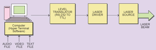
Transmitter
The data file in the PC, which is to be transmitted to another remote PC, is first converted into a serial bit stream in RS/EIA232 format with the help of hyper terminal software that comes with MS Windows and is available on the PC.
In the next step, this serial bit stream (representing data) is converted into TTL compatible pulses with the help of integrated circuit (IC) MAX232. This is a dual EIA232 driver/receiver. It has two on-chip independent EIA232-to-TTL/CMOS drivers and two on-chip independent TTL/CMOS-to-EIA232 receivers. On the transmitter side, one of the receivers has been used to convert the EIA232 bit stream into equivalent 5-volt TTL/CMOS-compatible pulses.
The TTL-compatible output pulses are then fed to a non-inverting adder circuit configured around the low- noise op-amp LM324. The other input to the adder is a DC voltage, which can be adjusted from approximately 0.5 volt to 1.7 volts. The magnitude of TTL pulses is also adjustable. This is required to get the desired magnitude of the drive current through the laser diode. This circuit is part of the overall laser diode driver circuit.
The output of this circuit feeds a constant current source driver circuit configured around the op-amp LM324 and an npn Darlington transistor. The magnitude of constant current is given by the voltage appearing at terminal 3 of this op-amp and the value of resistance RE.
The laser source used is a diode pumped solid state laser operating at 532 nm (green) with an output power of 10 mW. Green laser is used for underwater laser communication links, as it has the least attenuation in water. The proposed high-power green laser, which combines high power and high brightness with low signal noise at high repetition rates, has a great potential.


