Stepper motors are a mainstay in precision control systems, valued for their simple open-loop operation and high torque at low speeds. Commonly found in CNC machines, 3D printers, and robotics, they offer reliable motion control—yet their open-loop nature leaves them vulnerable to missed steps, overheating, and mechanical wear. Introducing a closed-loop PID (proportional-integral-derivative) control system significantly improves performance, enabling real-time monitoring to predict and prevent failures.
POC Video Tutorial:
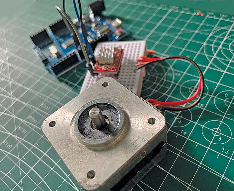
This system integrates a PID algorithm with predictive and preventive fault detection, implemented on an Arduino microcontroller and simulated using Proteus. Before exploring the implementation, it helps to revisit the core principles of PID control and the formula used. The complete list of required components is provided in the Bill of Materials table. The prototype is shown in Fig. 1.
PID control algorithm
Once the PID formula was developed, the design, proceeded with material selection. The PID controller is a feedback loop mechanism widely used in industrial control systems. It calculates an error value as the difference between a desired setpoint (SP) and a measured process variable (PV). The controller then attempts to minimise this error by adjusting the control inputs accordingly. For further details and the PID formula, refer to standard textbooks or verified online resources.

Tuning the PID parameters is crucial for effective control. The proportional gain (Kp) helps reduce steady-state error but may cause oscillations if set too high. The integral gain (Ki) eliminates residual error by accumulating past errors over time. The derivative gain (Kd) improves system stability and reduces overshoot by responding to the rate of change in error.
Advanced PID techniques improve performance in complex environments. Anti-windup mechanisms prevent excessive accumulation of the integral term when the actuator reaches its limits. Cascade control uses multiple PID loops in a hierarchical structure to manage multi-stage systems more effectively. Feedforward control anticipates known disturbances and compensates for them in advance.
| Bill of Materials | ||
| Component | Description | Quantity |
| Stepper motor (M1) | NEMA 17, 1.8° step angle | 1 |
| Motor driver (DR1) | A4988 or DRV8825 stepper driver | 1 |
| Microcontroller (MOD1) | Arduino Uno | 1 |
| Encoder (MOD2) | Rotary encoder for position feedback | 1 |
| Temperature sensor (S1) | LM35 temperature sensor for overheating detection | 1 |
| Current sensor (S2) | ACS712 current sensor for current monitoring | 1 |
Circuit and working
Fig. 2 shows the circuit diagram of the predictive failure control system for stepper motors. It is built around an Arduino Uno board (MOD1), an encoder (MOD2), a temperature sensor (S1), a current sensor (S2), a motor driver (DR1), and several additional components.