This cost-effective 433MHz wireless relay switch circuit allows remote relay control using an RF transmitter and receiver module. It is ideal for scenarios where wired connections are impractical or undesirable, such as remote lighting, wireless home automation, garage door control, or DIY IoT devices.
The system utilises a widely available, low-cost 433MHz RF transmitter-receiver pair. The transmitter sends digital on/off signals, which the receiver detects to trigger the relay.
POC Video Tutorial
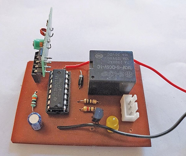
The SPDT relay at the receiver end operates on a 5V supply, depending on the load and power source. The switch offers a typical range of 50-100 metres in open areas and can penetrate walls with reduced performance. It provides a practical and reliable solution for wireless control applications. Fig. 1 shows the author’s receiver prototype.

433MHz Wireless RF Relay Switch Circuit and Working
The circuit of this 433MHz wireless relay switch consists of two main sections. One is the transmitter, whose circuit diagram is shown in Fig. 2. The second is the receiver, whose circuit diagram is shown in Fig. 3. The transmitter section utilises a 433MHz RF transmitter module (TX1) with three pins: data, Vcc, and ground. The data pin is connected through a 1k resistor (R4) to a push-to-on switch (S1), which also connects to the +5V supply. The Vcc pin is directly powered by +5V, while the ground pin is connected to the system ground (power). To improve signal transmission, a 7cm wire can be connected to the antenna terminal of the transmitter module.