


This system integrates traditional AC grids with DC systems, such as solar panels, batteries, and EV chargers, and coordinates them through software, automation, and cloud platforms. In a conventional electrical grid, electricity flows from power generation stations to consumers, and when generation and consumption remain balanced, the grid operates efficiently.
When load (power demand) increases, the generator turbines experience additional mechanical stress, causing a reduction in their rotational speed. This decrease in speed results in a drop in frequency, which in turn leads to a decline in voltage. When voltage and frequency fall below normal thresholds, electrical equipment at the consumer end may malfunction. If this condition persists, the generated power becomes unstable and ineffective, and generators disconnect automatically to safeguard the system.
POC Video Tutorial
Preventing such instability requires reducing loads during these conditions. Traditionally, this reduction has been carried out manually at substations. Advancements in technology have enabled these operations to be automated, forming the basis of what is known as a smart grid.
In many countries, alternating current (AC) is distributed to consumers via transmission lines. With the growing adoption of DC-based devices, such as electric vehicles, and renewable energy sources, such as solar panels, integrating AC and DC systems has become increasingly important.
A system that combines AC and DC power networks is called a hybrid smart grid. These systems improve energy management efficiency and optimise power utilisation. This hybrid smart grid system is designed as a cost-effective, educational platform that enables students, engineers, and designers to study and extend the concept for future applications.
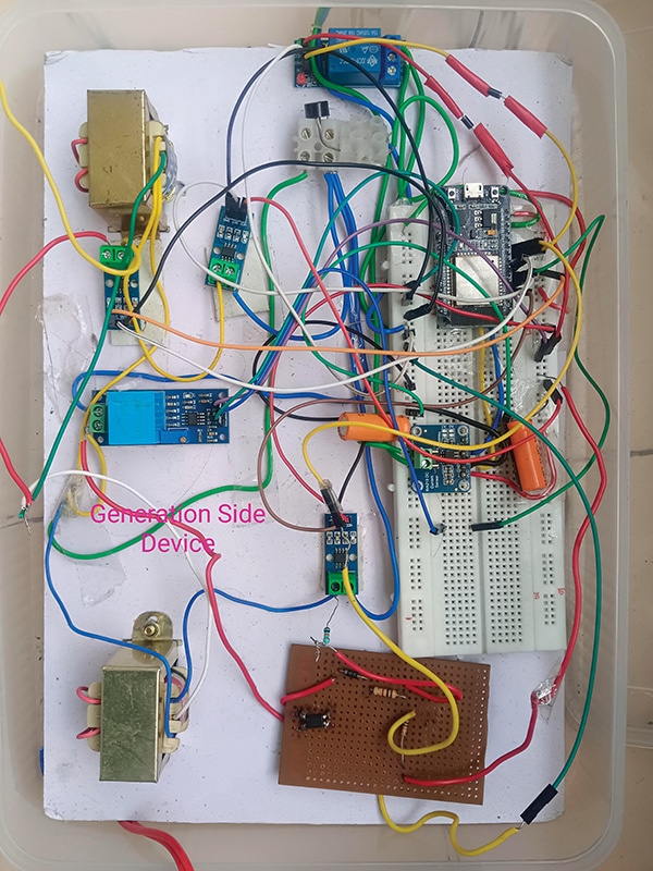
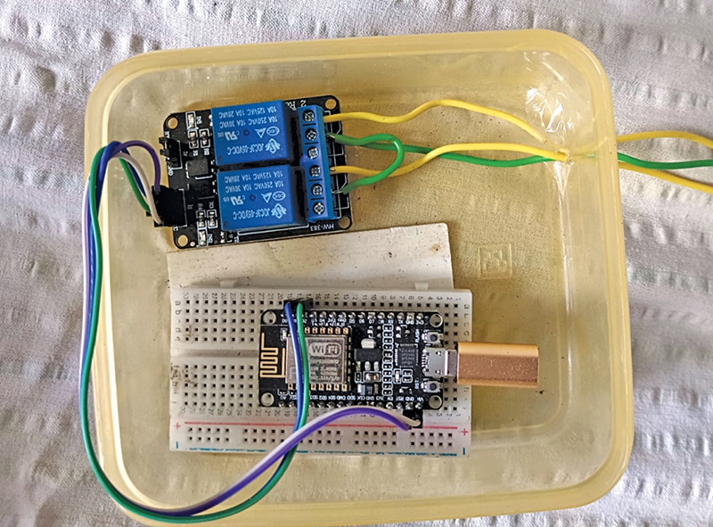
The system includes two modules: one for the generator side and one for the load side. The load side uses the ESP8266 and a relay module, as shown in Fig. 1. The generator side uses the ESP32 along with voltage and current sensors, as shown in Fig. 2. The components required to assemble the system are listed in the Bill of Materials table.
| Bill Of Materials | ||
| Components | Name | Quantity |
| ESP32 WROVER | MOD1 | 1 |
| ESP 8266 | MOD2 | 1 |
| INA219 current and voltage sensor | S5 | 1 |
| Buzzer | BZ1 | 1 |
| ZMPT101B voltage sensor | S1 | 1 |
| ACS712 current sensor | S2, S3, S4 | 3 |
| Single channel relay 5V | RL1 | 2 |
| PC817 optocoupler | IC1 | 1 |
| 1N4007 diode | D1 | 1 |
| 230V AC/9-0-9V, 4A transformer | G1, G2 | 2 |
| SS54L diode | D3, D4 | 2 |
| 12KΩ resistor | R1 | 1 |
| 10KΩ resistor | R2 | 1 |
| 1000µF, 25V electrolytic capacitor | C1 | 1 |
| Bridge rectifier (KBL06 ) | RT1 | 1 |
Hybrid AC–DC Smart Grid Design
The entire system is divided into three main sections.
1. Transmission line section
This section manages both AC and DC power sources along with their respective loads. For safety, the 230V AC supply is stepped down to 18V AC using two transformers. The current from each generating station is measured using ACS712 sensors (G1 and G2), while earth-fault current is monitored using another ACS712 sensor. AC voltage on the generation side is measured through a ZMPT101B sensor, and grid frequency is detected using an optocoupler (PC718) interfaced with an ESP32 microcontroller.
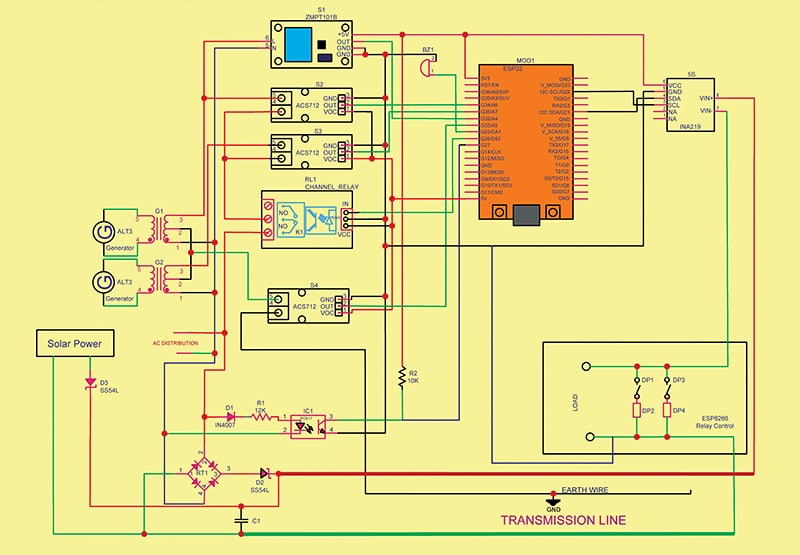
The AC power is converted to DC using a rectifier and fed into the DC transmission line, where voltage and current are monitored using an INA219 sensor. As solar power increases, the current drawn from the AC source decreases, reducing fuel injection in the thermal generator and improving energy efficiency.
The DC voltage derived from the AC supply is kept slightly lower than the solar panel’s output voltage, enabling automatic switching between sources. During daytime, when solar voltage is higher, the diode on the solar side becomes forward-biased and supplies power to the load, while the diode on the AC-derived DC side remains reverse-biased.
At night or in low-light conditions, when solar voltage falls below the AC-derived DC voltage, the diode on the DC side conducts and powers the load, while the solar-side diode becomes reverse-biased. This arrangement ensures seamless and automatic source selection.
2. Generation side control
