Drones are widely used across several fields, including aerial photography, surveying, inspection, agriculture, and recreation. Despite their growing importance, many drones develop hardware faults such as motor disconnection, ESC faults, missing propellers, overcurrent conditions, or low battery voltage before take-off. These issues can cause sudden imbalance, crashes, costly component damage, and loss of user confidence.
Apart from software diagnostics or GPS-based checks, drone controllers typically perform only basic system checks. As a result, critical faults often remain undetected. This system introduces a smart drone safety mechanism that functions as a pre-flight safety guardian. It monitors motor current and battery voltage using a precision current sensor and a voltage divider network. With a single button press, the ESC powers the motor for a short, controlled test cycle while the system analyses real-time current behaviour and battery health.
POC Video Tutorial:
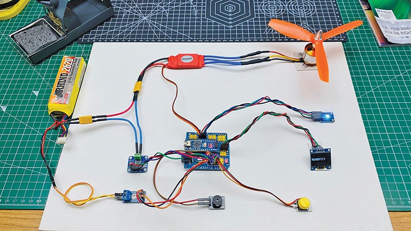
Very low current may indicate ESC disconnection or non-responsiveness. Low current may also suggest loose motor wiring or partial disconnection. Mid-range current indicates that the motor is operating without a propeller. Excessive current points to an overloaded or mechanically stressed motor, while low voltage indicates a weak or unsafe battery condition. Fig. 1 shows the author’s prototype.

Using carefully defined thresholds, the system accurately classifies each fault before the drone take-off stage. If an unsafe condition is detected, the system immediately shuts down the motor and provides clear feedback via an OLED display, RGB LED indicators, and a buzzer. Instead of guessing or interpreting raw values, the user receives a direct explanation of the issue.
The smart drone safety system is a standalone safety module designed to prevent damage to motors, ESCs, batteries, and frames. It reduces trial-and-error troubleshooting and serves as a quick diagnostic tool for technicians. Additionally, it acts as an educational platform for students and drone builders by demonstrating real motor behaviour through measurement-based analysis.
This system is simple, affordable, and practical. It can be used during assembly, maintenance, or routine pre-flight checks, improving reliability and promoting safer drone operation. The system also supports future expansion, including multi-motor testing, data logging for long-term motor health tracking, and wireless monitoring integration. The components required to build this system are listed in the Bill of Materials Table 1.
| Table 1: Bill of Materials | |
| Components | Quantity |
| Arduino Nano (MOD1) | 1 |
| Arduino Nano expansion board | 1 |
| 2.4cm (0.96”) I2C OLED display (OLED) | 1 |
| Buzzer module (B1) | 1 |
| INA219 current sensor module (S1) | 1 |
| Voltage sensor module (S2) | 1 |
| Electronic speed controller (ESC) | 1 |
| BLDC motor (M1) | 1 |
| RGB LED module (U2) | 1 |
| Push button switch (SW1) | 1 |
| 220Ω resistor (R1) | 1 |
| 10kΩ resistor (R2) | 1 |
| Jumper wires (male-male/mixed) | As required |
| 12V Li-Po drone battery (U1) | 1 |
Check the best electronics components online stores in India to buy these components.
Software coding
The Arduino IDE platform is used to write, compile, and upload code to the Arduino board. It supports C/C++-based programming, provides a simple user interface, includes built-in libraries, offers serial monitoring, and ensures cross-platform compatibility. This environment makes embedded system development accessible for both beginners and professionals.
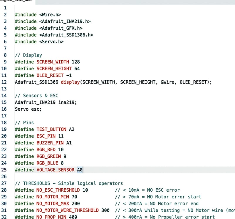
The INA219 sensor is used to measure current, while the SSD1306 OLED display is used for data visualisation. To interface these devices, the libraries Adafruit_INA219.h, Adafruit_GFX.h, and Adafruit_SSD1306.h must be installed using the Library Manager.
After installing the required libraries, the pins for the sensors, RGB LED, and ESC PWM signal are defined in the code. The Servo library generates the PWM signal required to control the ESC. Fig. 2 shows a snippet of the source code. The program displays the system status using the RGB LED, and the corresponding RGB status indications are listed in Table 2.
| Table 2 RGB LED status indication | ||
| RGB Colour | Status Meaning | Description |
| Cyan (blue+green) | Idle/ready | The system is powered on and ready for testing |
| Red (solid) | Testing /no power | Motor test is running or no battery |
| Red (blinking) | Low power | Battery voltage is low, unsafe to start the motor |
| Yellow (red+green) | Error/fault | Fault detected (ESC, motor, propeller, overload, wiring issue) |
| Green | Success | Motor, ESC, and power system are working correctly |
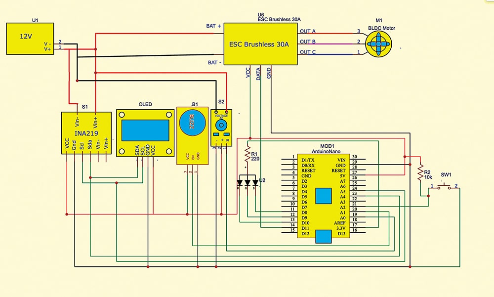
Circuit and working
Fig. 3 shows the circuit diagram of the BLDC motor failure detection system for drone safety. The system is built around an Arduino Nano, an INA219 current sensor module, an electronic speed controller (ESC), a BLDC motor, a 2.4cm (0.96-inch) I²C OLED display, an RGB LED, a voltage sensor module, and several supporting components.