


The controller area network (CAN) bus is a reliable, real-time communication protocol and remains the backbone of modern automotive, electric vehicle, aerospace, and marine systems. It enables the seamless integration of sensors into existing systems by facilitating communication between sensors, actuators, and electronic control units (ECUs) using just two wires.
POC Video Tutorial
Advanced driver-assistance systems (ADAS), lidar, and radar sensors often need to coexist on the same CAN network without increasing system complexity or cost. To address this challenge, this CAN-bus-based Doppler radar and IMU (inertial measurement unit) sensor system is designed for easy integration into existing vehicle architectures.
The system combines an HB100 Doppler radar with an LSM303AGR IMU and transmits all critical data over the vehicle’s native CAN bus using standard 11-bit identifiers (0x100, 0x200, and 0x300). This direct compatibility eliminates the need for gateways or protocol conversions, ensuring seamless integration with other ECUs.
The Doppler radar accurately measures the relative speed between the host vehicle and surrounding objects using the Doppler effect. This relative velocity data is crucial for ADAS applications such as collision avoidance, adaptive cruise control, and autonomous braking. While many such systems are laser-based, they may not perform reliably in foggy or very low-light conditions. In contrast, the Doppler radar operates effectively in all lighting conditions, including fog, and is capable of measuring very high speeds that many other systems cannot.
The integrated IMU provides real-time acceleration and orientation data (yaw, roll, and pitch) and detects critical events, including sudden acceleration, braking, collisions, rollovers, and free fall. All sensor data, including Doppler frequency, relative speed, acceleration, temperature, orientation, and event flags, is transmitted in real time over the CAN bus, enabling other ECUs and controllers to instantly use the data for decision-making.
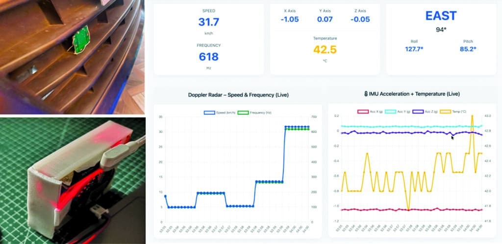
Furthermore, the module features built-in IoT capabilities via Wi-Fi, enabling wireless monitoring of all radar and IMU parameters via a clean, responsive web dashboard accessible on any laptop or smartphone. This dual-interface design, combining CAN bus and Wi-Fi, makes the radar module highly versatile. It can be seamlessly integrated into existing vehicle CAN networks as a plug-and-play solution or used as a powerful development tool for building advanced ADAS and vehicle monitoring systems (see Fig. 1).
As shown in Fig. 1, a CAN bus radar is mounted on the vehicle’s bonnet. On the right side, the radar data is displayed wirelessly on the IoT dashboard provided by the module itself. The components required to build this system are listed in the Bill of Materials table.
| Bill Of Materials | ||
| Name | Designator | Quantity |
| IndusBoard coin | U1, U5 | 2 |
| HB100 radar | S1 | 1 |
| LM358 amplifier | U3 | 1 |
| CAN bus TJA1050 module | U2, U6 | 2 |
| OBD port connector | U4 | 1 |
| Twisted connector wires | 1 | |
| 3D printed enclosure | 1 | |
| USB-C cable | 1 | |
CAN bus design
Unlike traditional communication systems that require separate wires for each device, the CAN bus connects all ECUs and sensors using only two twisted wires: CAN High and CAN Low. In a multi-master configuration, all ECUs share the same bus. Any ECU can transmit messages at any time, and every node on the bus receives the data. Each ECU then decides whether to process or ignore the message based on its identifier.
The twisted-pair wiring effectively rejects electromagnetic interference, ensuring reliable communication in noisy vehicle environments. Data is transmitted by varying the voltage difference between the two wires: a dominant state (logic 0) produces a 2V differential, while the recessive state (logic 1) keeps both wires at approximately 2.5V. This simple and robust design enables efficient, real-time data sharing among all devices with minimal wiring.
How doppler radar works
