





A bi-directional Li-Fi (light fidelity) optical communication system has been developed for high-speed, two-way digital data transfer over free-space optical links. Using laser diodes, photodiodes, and on-off keying (OOK) modulation, each module can operate dynamically as both a transmitter and a receiver, unlike the earlier unidirectional design published in June issue of EFY. This enables reliable bi-directional communication over the same optical link at data rates of up to 520kbps.
POC Video Tutorial
The system uses dedicated transmitter and receiver circuits with switching logic, together with handshake, packet-based communication, and checksum-based error detection to ensure reliable transfer of files of any type. It demonstrates the practical implementation of full-duplex optical wireless communication using low-cost discrete components and USB-to-TTL converters, making it suitable for academic study, system development, and rapid prototyping as an alternative to conventional RF communication. Fig. 1 shows the author’s breadboard prototype. Two identical system units were built and tested.
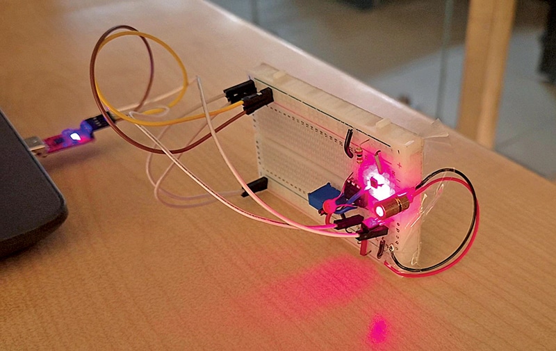
Circuit and working
Fig. 2 shows the circuit diagram of the Li-Fi transceiver module for bi-directional optical communication. It consists of two identical transceiver units, each capable of functioning as both a transmitter and a receiver. Each unit is built around a CH9102 USB-to-TTL converter (U1), an LM393 dual comparator (IC1), a BC547 transistor (T1), a laser diode (LD1), and a BPW34 photodiode (D1). Of the two comparators in the LM393, only IC1B is used, while IC1A remains unused.
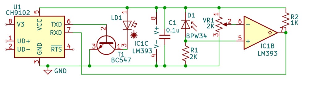
On the transmitter side, the TXD (pin 6) output of the CH9102 drives transistor T1, which switches the laser diode on and off according to the serial data, thereby implementing on-off keying (OOK) modulation. The optical pulses are transmitted through free space to the receiving unit.
In the receiver section, the BPW34 photodiode is reverse-biased through R1 (2kΩ) and generates a voltage proportional to the received light intensity. This signal is applied to the non-inverting input (pin 5) of comparator IC1B. The inverting input (pin 6) receives an adjustable reference voltage from potentiometer VR1, allowing the detection threshold to be optimised for ambient light conditions and improved noise rejection. Resistor R2 acts as the pull-up resistor for the LM393’s open-collector output, while capacitor C1 (0.1µF) provides supply decoupling to improve stability at high switching speeds. The comparator converts the weak analogue signal into clean TTL-level pulses, which are fed to the RXD (pin 7) of the CH9102 for USB serial communication.
During operation, the software alternately switches each unit between transmit and receive modes. Since both transceiver units use identical hardware, either unit can transmit or receive data at any time. This arrangement enables reliable bi-directional optical communication with handshake and error-checking support at data rates of up to 520kbps.
| Parts List (For one set) |
| Semiconductors: LD1 – Laser diode T1 – BC547 npn transistor D1 – BPW34 pin photodiode IC1 (IC1A-IC1C) – LM393 comparator Resistors (all 1/4-watt, ±5% carbon): R1 – 2kΩ R2 – 1kΩ VR1 – 2kΩ potmeter Capacitors: C1 – 0.1µF ceramic disc Miscellaneous: U1 – CH9102 USB to TTL converter module – PCB (designed or custom-made) or Breadboard – Connecting/jumper wires – Enclosure (optional) |
The software

Hi,
Can you please provide the part number of the laser diode?
Don’t you require a TIA after the BPW34?
Is it possible to share the video of the demonstration?
Hi, we have used generic 650 nm laser diode (KY-008 compatible) for this proof of concept, which is easily available on online as well as offline stores.
TIA is skipped here because of concentrated laser source where the signal reception strength is massive and doesn’t require further amplification before the comparator.
Video demonstration for your reference: https://www.youtube.com/watch?v=4XlFXwei5o4
Nice one Abhay!
Pleasure reading it.
The video claims that the receiver asks for corrupted bytes. How does the receiver communicate back to the transmitter? What distance is tested?
Hi Rajesh, as it is a bidirectional link, both the modules are transreceivers, so they can transmit and receive the data simultaneously. If the link is disconnected due to obstacles, poor alignment or senstivity during transmission, the receiver will not receive the complete packet data in this case and will send re-transmission message for that specific packet, until that packet is not completely received. Similarly, it also sends a verification message after every successful received packet, and the sender verifies the message and proceed with transmission of next packet.
This Lifi link is tested at 5 metres distance without errors.