




SolarSentinel-X: AI-Powered Self-Sustaining Wireless Solar Panel Health Monitoring and Autonomous Cleaning System is an AIoT-based solution designed to monitor photovoltaic panel performance and automate cleaning when required. The system uses an ESP32-S3 as the central controller and Edge AI processor, integrating a BH1750 light sensor, INA219 current sensor, voltage-sensing module, DS18B20 temperature sensor, and LDR module to evaluate environmental and electrical operating conditions. Instantaneous power is calculated from the measured voltage and current using (P = V \times I). An embedded Decision Tree analyses light intensity, panel voltage, and current locally to determine the appropriate system response and initiate autonomous cleaning when the defined conditions are satisfied. A relay-controlled water pump and an MG90S servo-operated cleaning mechanism perform the cleaning operation. The system also incorporates an OLED display, LoRa wireless communication using the SX1278/RA-02 module, a web-based monitoring dashboard, and an independent W1209 temperature controller. By combining real-time sensing, on-device intelligence, wireless telemetry, and automated maintenance, SolarSentinel-X aims to reduce manual intervention and improve the efficiency of solar-panel monitoring and maintenance.
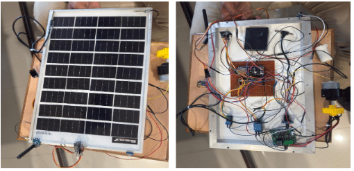
Team Members
| S. No. | Name | Role / Contribution |
| 1 | M. Abhinav | Embedded Systems, ESP32-S3 Firmware, Edge AI and System Integration |
| 2 | G. Nitya Sri | Hardware Design, Sensor Integration, Power System and Prototype Development |
| 3 | G. Eshwar | LoRa Communication, Web Dashboard and Software Integration |
Project Overview
SolarSentinel-X is an AIoT-based intelligent solar-panel monitoring and autonomous maintenance system designed to continuously observe the operating condition of a photovoltaic panel and initiate a cleaning operation when the detected condition requires it.
The system combines embedded sensing, Edge AI, wireless communication, local visualisation, web-based monitoring and autonomous mechanical cleaning in a single prototype.
An ESP32-S3 acts as the central controller and Edge AI processor. It receives information from multiple sensors installed around the solar panel. These sensors monitor the illumination level, electrical output, panel temperature and day/night condition.
The system uses a BH1750 light sensor for light-intensity measurement, an INA219 for current measurement, a voltage-sensing module for panel voltage, a DS18B20 for panel temperature and an LDR module for day/night detection.
The measured voltage and current are also used to calculate the instantaneous electrical power: P=V x I
The main intelligence of the system is implemented directly on the ESP32-S3 through an embedded Decision Tree. The current Decision
Tree uses three principal inputs:
- Light intensity
- Panel voltage
- Panel current
The AI decision is processed locally on the ESP32-S3 rather than depending on a remote computing platform for the primary decision.
When the cleaning condition is confirmed, the ESP32-S3 activates the autonomous cleaning system. A relay controls the water pump, while an MG90S servo motor operates the mechanical cleaning movement.
The system simultaneously provides information through an OLED display, a wireless SX1278/RA-02 LoRa communication link, and a web-based dashboard.
A W1209 temperature controller is also incorporated as an independent temperature-control subsystem.
The resulting architecture creates a complete AIoT cycle:
Sense → Process → Analyse → Decide → Act → Communicate → Monitor
Problem Statement
Solar panels operate outdoors and are continuously exposed to environmental conditions.
Dust and other contaminants can accumulate on the photovoltaic surface. At the same time, solar-panel voltage, current, illumination and temperature continuously change with operating conditions. Conventional maintenance generally depends on periodic inspection and manual cleaning. Such an approach does not continuously evaluate the actual condition of the panel and requires human intervention.
SolarSentinel-X addresses this problem by developing an intelligent embedded system that can:
- Monitor the panel continuously
- Measure important operating parameters
- Analyse measurements using Edge AI
Determine an appropriate operating condition
- Initiate an autonomous cleaning operation
- Transmit telemetry wirelessly
- Display system information locally and remotely
Objectives
The objectives of SolarSentinel-X are:
- To develop an intelligent solar-panel monitoring system.
- To continuously acquire photovoltaic and environmental parameters.
- To measure panel voltage and current.
- To calculate instantaneous panel power.
- To monitor solar-panel temperature.
- To detect day and night conditions.
- To implement Edge AI on the ESP32-S3.
- To use a Decision Tree for operating-condition classification.
- To automatically initiate the cleaning mechanism when the required condition is confirmed. 10.To control a water pump automatically.
- To control a servo-based mechanical cleaning mechanism.
- To transmit telemetry through LoRa.
- To provide local information through an OLED display.
- To provide real-time information through a web dashboard.
- To incorporate an independent W1209 temperature-control subsystem.
- To demonstrate an end-to-end AIoT solution using a functional physical prototype.
Proposed Solution
SolarSentinel-X consists of five major subsystems:
1. Sensing subsystem
Collects information from the solar panel and its surrounding environment.
2. Edge intelligence subsystem
Uses the ESP32-S3 to process measurements and execute the Decision Tree.
3. Autonomous cleaning subsystem
Uses a water pump and servo-driven mechanism to perform physical cleaning.
4. Wireless communication subsystem
Uses the SX1278/RA-02 LoRa module to transmit telemetry.
5. Monitoring subsystem
Uses an OLED and web dashboard to present system information.
Complete System Architecture
The architecture consists of the following data and control paths.
Sensor path
The sensors continuously provide measurements to the ESP32-S3.
AI path
The principal AI inputs are light intensity, voltage and current.
Control path
The AI and system-state logic determine whether the system should remain in monitoring mode or initiate cleaning.
Actuator path
The cleaning controller operates the relay-controlled pump and MG90S servo.
Communication path
The ESP32-S3 prepares telemetry information and transmits it through the RA-02 LoRa module.
Visualization path
The latest information is presented locally through the OLED and through the web dashboard.
List of Components
| ID | Component | Designator | Quantity | Function |
| 1 | ESP32-S3 Development Board | MOD1 | 1 | Main controller and Edge AI processor |
| 2 | Solar Panel | SP1 | 1 | Renewable energy source and monitored PV surface |
| 3 | BH1750 Light Sensor | S1 | 1 | Light-intensity measurement |
| 4 | INA219 Current Sensor | S2 | 1 | Current measurement |
| 5 | Voltage Sensor Module | S3 | 1 | Solar-panel voltage measurement |
| 6 | DS18B20 Temperature Sensor | S4 | 1 | Solar-panel temperature measurement |
| 7 | LDR Module | S5 | 1 | Day/night detection |
| 8 | SX1278 / RA-02 LoRa Module | RF1 | 1 | Wireless telemetry |
| 9 | OLED 128×64 Display | OLED1 | 1 | Local system monitoring |
| 10 | MG90S Servo Motor | SERVO1 | 1 | Cleaning mechanism movement |
| 11 | Water Pump | PUMP1 | 1 | Water delivery for cleaning |
| 12 | Relay Module | RL1 | 1 | Pump switching |
| 13 | W1209 Temperature Controller | TC1 | 1 | Independent temperature control |
| 14 | Battery | BAT1 | 1 | Energy storage |
| 15 | Charging/Protection Circuit | PM1 | 1 | Battery charging and protection |
| 16 | Voltage Regulation Circuit | PM2 | 1 | Regulated power supply |
| 17 | Water Tubing | MECH1 | As required | Water delivery |
| 18 | Mechanical Cleaning Assembly | MECH2 | 1 | Physical cleaning |
| 19 | Prototype Board/Breadboard | HW1 | As required | Hardware assembly |
| 20 | Connecting Wires | HW2 | As required | Electrical interconnection |
Detailed Components Description
ESP32-S3
The ESP32-S3 is the central controller of SolarSentinel-X.
It performs:
- Sensor acquisition
- Data processing
- Power calculation
- Edge AI inference
- Cleaning control
- OLED control
- LoRa communication
- Web-server operation
- System-status management
The ESP32-S3 was selected because it provides sufficient processing capability and peripheral interfaces for integrating sensing, communication and actuator control within a compact embedded system.
The controller effectively acts as the central bridge between the physical solar-panel system and the digital AIoT layer.
Solar Panel
The solar panel is the primary photovoltaic element of the prototype.
It has two roles.
First, it represents the renewable-energy source.
Second, it is the physical surface whose operating condition is monitored and maintained.
The electrical output of the panel is monitored using voltage and current sensing.
The controller uses: P=VxI
to determine instantaneous electrical power.
The solar panel is also integrated with the physical cleaning mechanism so that the monitoring and maintenance functions operate on the same photovoltaic surface.
BH1750 Light Sensor
The BH1750 measures ambient light intensity in lux.
The sensor communicates digitally with the ESP32-S3.
The light measurement is used for:
- Environmental monitoring
- Daylight assessment
- Edge AI
- Web dashboard
- OLED display
- LoRa telemetry
The BH1750 is one of the three principal Decision Tree inputs.
Data path
Ambient Light → BH1750 → ESP32-S3 → Decision Tree
VOLTAGE SENSOR
The voltage-sensing module measures the electrical voltage produced by the solar panel.
Since the ESP32-S3 uses a low-voltage ADC input, the sensing circuit scales the measured panel voltage to a suitable level for the controller.
The voltage measurement is used for:
- Solar-panel monitoring
- Power calculation
- Edge AI
- Dashboard visualisation
- Telemetry
The voltage therefore forms an important part of the electrical-health information available to the system.
INA219 Current Sensor
The INA219 measures the electrical current of the monitored circuit.
Current is required together with voltage to calculate electrical power.
The ESP32-S3 performs:P=VxI
The current measurement is also one of the three principal Decision Tree inputs.
This allows the AI system to consider electrical operating behaviour rather than relying only on an environmental sensor.
DS18B20 Temperature Sensor
The DS18B20 measures the temperature of the solar panel.
The sensor provides digital temperature information to the ESP32-S3.
Temperature is important because the physical and electrical behaviour of photovoltaic panels changes with temperature.
The temperature value is used for:
- Monitoring
- Dashboard display
- OLED display
- Telemetry
- System condition information
The DS18B20 is not one of the current Decision Tree inputs. It is used as a separate temperature-monitoring channel.
LDR MODULE
The LDR module is used to identify whether the system is operating under daylight or low-light conditions.
The resistance of an LDR varies according to incident light.
The ESP32-S3 interprets the LDR output and generates the day/night state.
The dashboard represents this condition as:
DAY / NIGHT
This allows the system to distinguish solar operating periods from periods of low illumination.
SX1278 / RA-02 LoRa Module
The SX1278/RA-02 provides wireless communication between the SolarSentinel-X monitoring node and the custom receiver.
The ESP32-S3 collects the latest measurements and system state and forms a telemetry packet.
A representative packet structure is:
DAY=1,
LUX=…,
V=…,
I=…,
P=…,
TEMP=…,
STATUS=…,
CLEAN=0/1
The receiver can decode this information for monitoring and validation.
No communication-range specification is claimed for the prototype.
OLED Display
The 128×64 OLED provides local visualisation.
It can display:
- Light intensity
- Voltage
- Current
- Power
- Temperature
- Day/night state
- Panel status
- Cleaning status
This allows the system to be observed directly at the hardware without requiring a computer or remote dashboard.
The OLED is particularly useful during prototype testing and demonstration.
MG90S Servo Motor
The MG90S servo motor provides controlled mechanical movement for the cleaning system.
The ESP32-S3 sends a control signal to the servo.
During the cleaning process, the servo performs a programmed sweep across the panel-cleaning mechanism.
The movement can be represented as:
LEFT → RIGHT → LEFT → HOME
After completing the programmed movement, the servo returns to its home position.
The servo therefore converts the digital cleaning decision into physical mechanical action.
Water Pump
The water pump supplies water to the cleaning mechanism.
The pump is controlled through a relay.
The controller does not directly drive the pump motor.
Instead:
ESP32-S3 → Relay Control → Relay → Pump
This arrangement allows the low-power microcontroller to control the higher-power pump circuit.
Relay Module
The relay acts as the electrical switching interface for the water pump.
The ESP32-S3 produces a control signal.
The relay responds to that signal and switches the pump’s external power circuit.
This separates the microcontroller’s control signal from the pump’s power path.
W1209 Temperature Controller
The W1209 is implemented as an independent temperature-control subsystem.
It is separate from the ESP32-S3 Edge AI decision system.
The W1209 uses its own temperature sensing and control circuitry and can switch a connected thermal-management load according to the configured temperature-control condition.
Its operation can be represented as:
Temperature sensing → W1209 controller → Relay → Thermal load
Meanwhile, the ESP32-S3 independently monitors the panel temperature using the DS18B20.
Therefore:
DS18B20 = ESP32-S3 temperature monitoring
W1209 = independent temperature control
The W1209 is not used to control the cleaning mechanism and is not an input to the current Decision Tree.
Battery and Power System
The battery provides energy storage for the system.
The solar panel provides the energy source, while the battery allows energy to be stored and made available to the electronics and actuators when required.
The power system includes the following:
- Charging circuitry
- Battery protection
- Voltage regulation
Distribution: The regulated supply is then provided to the different electronic subsystems.
Charging and Protection Circuit
The charging and protection circuit is responsible for managing the battery charging arrangement and protecting the energy-storage subsystem.
It forms the interface between the photovoltaic energy source, battery and regulated system supply.
The exact charging and protection configuration should be selected according to the battery chemistry and electrical characteristics used in the final prototype.
Edge AI Implementation
SolarSentinel-X uses Edge AI rather than depending entirely on a remote cloud server. The Decision Tree is embedded directly in the ESP32-S3 firmware.
The three principal AI inputs are:
Input 1 — Light intensity
Obtained from the BH1750.
Input 2 — Voltage
Obtained from the voltage-sensing circuit.
Input 3 — Current
Obtained from the INA219.
The Decision Tree analyses these values and contributes to the operating-condition decision.
The overall AI path is:
BH1750 + Voltage Sensor + INA219
↓
ESP32-S3
↓
Embedded Decision Tree
↓
Operating Condition
↓
Monitor / Cleaning
Why EDGE AI?
Edge AI provides several advantages for SolarSentinel-X.
Local decision-making
The primary AI decision occurs directly inside the ESP32-S3.
Reduced dependence on cloud computing
The system does not need to send sensor information to a remote AI server before performing its core
decision.
Faster embedded response
The controller can directly use the AI result for actuator control.
Autonomous operation
The AI decision can trigger the cleaning mechanism without requiring manual intervention.
Better integration
The AI becomes part of the physical embedded system rather than being a separate software application.
Complete Working Principle
Stage 1 — System startup
The ESP32-S3 powers up and initialises the sensors, OLED, LoRa communication interface, servo
and other peripherals.
Stage 2 — Sensor acquisition
The controller acquires information from:
- BH1750
- Voltage sensor
- INA219
- DS18B20
- LDR
Stage 3 — Electrical calculation
The controller calculates instantaneous power:
\[ P=V\times I \]
Stage 4 — Environmental analysis
The system determines:
- Light intensity
- Day/night condition
- Panel temperature
Stage 5 — Edge AI processing
The light intensity, voltage and current are provided to the embedded Decision Tree.
Stage 6 — System decision
The controller determines whether the system should remain in monitoring mode or proceed to the cleaning sequence.
Stage 7 — Cleaning
When cleaning is confirmed, the pump is activated and the servo performs the programmed mechanical sweep.
Stage 8 — Communication
The ESP32-S3 generates a telemetry packet and transmits the system information using LoRa.
Stage 9 — Visualisation
The OLED and web dashboard are updated.
Stage 10 — Continuous operation
After completing the cleaning operation, the system returns to monitoring mode.
Web Dashboard
The web dashboard provides a simple interface for observing the operating condition of the prototype.
The dashboard displays:
- Day/night state
- Light intensity
- Voltage
- Current
- Power
- Temperature
- Panel status
- Cleaning status
During the demonstrated prototype operation, the dashboard displayed:
| Parameter Day/Night Light Voltage Current Power | Demonstrated Reading DAY 40,159.2 Lux 16.50 V 0.019 A 0.32 W |
Temperature 47.2 °C
Panel Status MONITOR
Cleaning OFF
These values are included as observed prototype readings from the demonstration, not as fixed specifications.
Local Monitoring
The OLED provides immediate information at the physical device.
This is particularly useful during:
- Hardware testing
- Sensor calibration
- Debugging
Demonstration ∙ Maintenance
The OLED eliminates the need to connect a computer simply to observe the current system state.
Testing and Validation
The prototype was tested progressively to verify the operation of individual subsystems and then the complete system.
Sensor testing
The sensors were tested individually to confirm communication and measurement acquisition.
Electrical monitoring
Voltage and current measurements were checked and used to calculate electrical power.
Temperature monitoring
The DS18B20 was tested for panel-temperature measurement.
Day/night detection
The LDR subsystem was tested to determine the day/night state.
OLED testing
The OLED was tested for local parameter visualization.
AI testing
The embedded Decision Tree was integrated into the ESP32-S3 firmware and tested with sensor inputs.
Cleaning testing
The pump and servo were tested as a combined cleaning mechanism.
Wireless testing
The RA-02 was integrated to transmit telemetry to the receiver.
Dashboard testing
The web dashboard was tested to display the current system measurements.
System-level testing
Finally, all subsystems were operated together to demonstrate the complete SolarSentinel-X workflow.
Observed Prototype Output
One demonstrated operating condition produced the following displayed values:
Parameter Value
Day/Night DAY
Light Intensity 40,159.2 Lux
Voltage 16.50 V
Current 0.019 A
Calculated Power 0.32 W
Temperature 47.2 °C
Panel Status MONITOR
Cleaning Status OFF
Innovation
SolarSentinel-X combines several technologies that are normally implemented as separate subsystems.
The key innovation is the integration of:
Multi-parameter sensing
The system monitors both electrical and environmental information.
Embedded Edge AI
The Decision Tree executes locally on the ESP32-S3.
Autonomous physical action
The system can convert the AI decision into a physical cleaning operation.
Wireless telemetry
LoRa provides communication between the monitoring node and receiver.
Local and remote visualization
The OLED and web dashboard provide two levels of user interaction.
Independent thermal control
The W1209 provides a separate temperature-control subsystem.
The resulting system is therefore not merely a solar monitoring device; it is an intelligent sensing-and-action platform.
Advantages
SolarSentinel-X provides the following advantages:
- Continuous solar-panel monitoring
- Embedded Edge AI
- Autonomous cleaning
- Wireless telemetry
- Local OLED monitoring
- Web-based monitoring
- Modular architecture
- Reduced dependence on manual inspection
- Direct AI-to-actuator integration
- Renewable-energy-oriented architecture
- Independent temperature-control capability
- Potential for multi-panel expansion
Applications
The SolarSentinel-X concept can be adapted for:
Residential solar installations
For monitoring rooftop solar panels.
Commercial installations
For intelligent monitoring and maintenance.
Industrial photovoltaic systems
For continuous monitoring of larger solar installations.
Solar farms
Multiple intelligent nodes can be deployed across distributed photovoltaic panels.
Remote renewable-energy installations
Wireless telemetry can reduce the need for continuous physical inspection.
Sustainability
SolarSentinel-X is designed around the concept of renewable-energy-powered monitoring.
The solar panel provides the energy source and the battery provides energy storage.
The system uses power-management circuitry to distribute appropriate supply levels to the electronics.
The autonomous cleaning mechanism is intended to reduce the dependence on manual cleaning.
The complete energy balance of the system should be established through actual measurements of generation, storage, electronics consumption and actuator consumption rather than estimated values.
Project Explaination
The working video demonstrates:
- Complete SolarSentinel-X prototype
- Solar panel
- ESP32-S3 controller
- Sensor integration
- OLED monitoring
- Web dashboard
- Sensor measurements
- Edge AI operation
- Cleaning mechanism
- Water pump operation
- Servo movement
- Wireless telemetry
- Complete system operation
Project Demonstration Flow
For the judges, the project can be presented in this order:
1. Show the complete prototype
Start with the complete solar panel and electronics.
2. Explain the sensing system
Point out the BH1750, INA219, voltage sensor, DS18B20 and LDR.
3. Show the ESP32-S3
Explain that it is the central controller and Edge AI processor.
4. Show the dashboard
Demonstrate real-time measurements.
5. Explain Edge AI
Explain that the Decision Tree uses light intensity, voltage and current.
6. Trigger the cleaning condition
Demonstrate the transition into the cleaning sequence.
7. Show the pump
Demonstrate water delivery.
8. Show the servo
Demonstrate the mechanical cleaning movement.
9. Show LoRa
Explain that telemetry is transmitted wirelessly.
10. Show OLED
Demonstrate local monitoring.
11. Explain W1209
Explain that it operates independently as the temperature-control subsystem.
12. End with complete system
Show the complete AIoT loop.
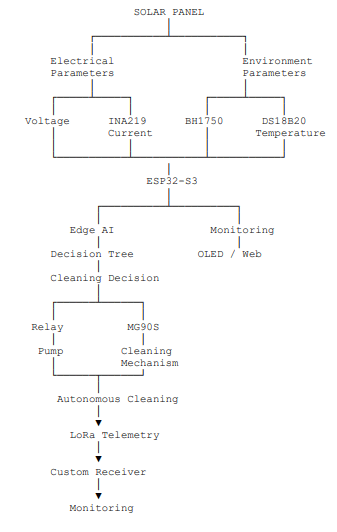
Final System Flow
The complete SolarSentinel-X system can be summarised as:
Conclusion
SolarSentinel-X demonstrates an integrated AIoT approach to intelligent solar-panel monitoring and autonomous maintenance.
The developed prototype combines a solar panel, multiple sensors, ESP32-S3 embedded processing, Edge AI, autonomous cleaning, LoRa communication, OLED visualization, web monitoring and an independent temperature-control subsystem.
The ESP32-S3 acts as the core of the system, collecting sensor information and performing the primary Edge AI decision locally. The current Decision Tree uses light intensity, panel voltage and panel current as its principal inputs.
When the required cleaning condition is confirmed, the system activates the water pump and operates the MG90S servo to perform the programmed cleaning sequence.
At the same time, the system can transmit telemetry through LoRa and provide information through both the OLED and web dashboard.
The project demonstrates the complete transformation of sensor information into an intelligent physical action:
SENSE → ANALYSE → DECIDE → ACT → COMMUNICATE → MONITOR
The completed prototype establishes a foundation for future development toward more robust mechanical construction, custom electronics, advanced AI models, quantitative performance validation and deployment across larger photovoltaic systems.
