




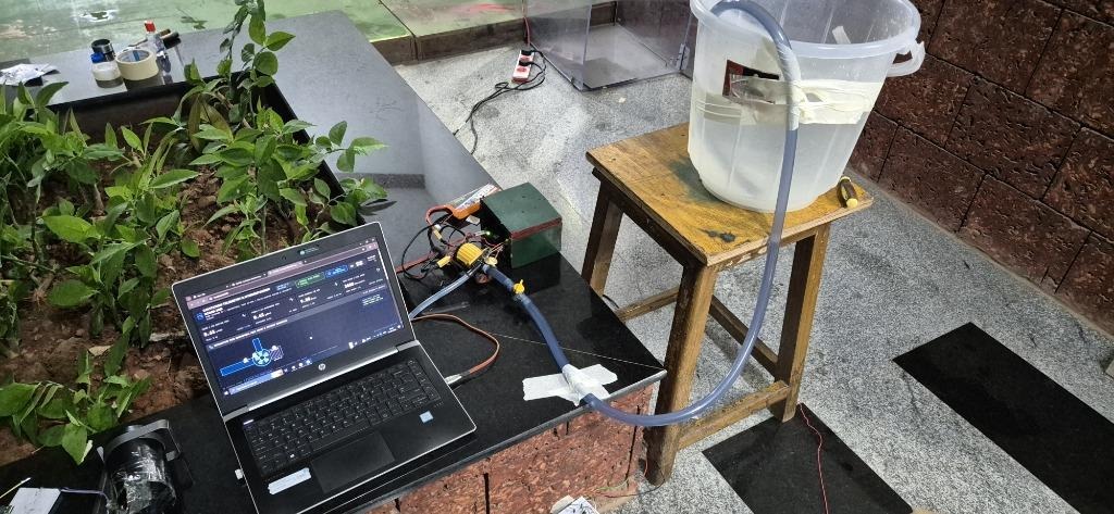
AIoT-Based Cavitation Detection and Adaptive Control System for Centrifugal Pumps is designed to detect early signs of hydrodynamic cavitation and optimise pump operation using multimodal sensing, Edge AI, and closed-loop control. The system integrates vibration sensors, an acoustic sensor, and motor-current sensing to capture changes in pump behaviour associated with cavitation. A real-time microcontroller acquires high-frequency sensor signals and performs Fast Fourier Transform (FFT) processing, while a Linux-based application processor extracts frequency-band features and executes an on-device Random Forest machine learning model to classify cavitation conditions. When cavitation is detected, an adaptive control mechanism uses PID-based feedback to adjust pump speed through a compatible motor driver or variable-frequency drive, aiming to reduce cavitation risk while maintaining efficient operation. The system also supports real-time telemetry, data logging, and dashboard-based monitoring for performance analysis. By combining non-invasive sensing, edge intelligence, and autonomous speed regulation, the proposed solution aims to minimise pump wear, reduce energy losses, and improve operational reliability in agricultural and industrial pumping applications.
Team Members
| S.No. | Name | Role / Contribution |
|---|---|---|
| 1. | Kapilmeet Singh | Team Leader: Embedded Systems Architect, Dual-Core RouterBridge IPC, Edge Physical AI Deployment & System Integration |
| 2. | Nikunj Singhal | Firmware Engineer: Low-Level Zephyr RTOS Fast ADC Driver Optimization, Ring Buffer Architecture & DMA Subsystem |
| 3. | Jaishnu R | Control Systems Engineer: Hydrodynamic Flow Dynamics, Net Positive Suction Head (NPSH) Modeling & Closed-Loop PID Control |
| 4. | Tanay Savio Saldanha | IoT & Software Engineer: Industrial AIoT Architecture, Real-Time SCADA HMI Web Telemetry Interface & Data Logging |
| 5. | Daivik Neogi | Acoustic & Mechanical Engineer: Acoustic Waveform Signal Processing, Transducer Enclosure Design, Testbed Rig Construction |
| 6. | Shreya Verma | Algorithm Engineer: Multi-Modal Sensor Fusion Architecture, High-Speed Onboard FFT Engine & Spectral Analysis |
| 7. | Tanya Singh | Hardware Design Engineer: Analog Front-End Signal Conditioning, High-Z Piezo Clamping Protection & Power Tree Hardware |
| 8. | Aashita Gupta | Data Scientist: Machine Learning Pipeline, 8–20 kHz Band-Power Feature Engineering, Random Forest Training & Validation |
Project Video & Code Access:
- Working Project Demonstration: https://www.youtube.com/watch?v=X3MLUWcRTSs
- Full Experimental Hydraulic Testing: https://drive.google.com/file/d/1NdSjHkZP5aevQ25KPRAulMcES6_8Juj5/view
- Official GitHub Repository: https://github.com/Kapilmeet/AIoT-Cavitation-Detection-and-Adaptive-Control
Component List (Bill of Materials)
| ID | Component Name & Technical Specification | Designator | Qty | Function / Purpose |
|---|---|---|---|---|
| 1 | Arduino UNO Q Single Board Computer (4GB, ABX00173) | MOD1 | 1 | Dual-core processing brain: STM32 core (Zephyr RTOS) for 50 kHz ADC + Linux processor for Edge AI & SCADA |
| 2 | Cytron 3Amp 4V–16V Dual Channel DC Motor Driver (MDD3A) | MDD1 | 1 | Solid-state H-bridge motor driver for PWM pump speed modulation |
| 3 | Piezoelectric Ceramic Disc Sensors (27mm Brass Backing) | PZ1, PZ2 | 2 | High-frequency acoustic emission / vibration pickup (PZ1: Suction, PZ2: Discharge) |
| 4 | Boya BY-M1 Omnidirectional Condenser Microphone | MIC1 | 1 | Acoustic bubble-collapse sound receiver (airborne cavitation crackle monitoring) |
| 5 | DC 12V 20W Brushless Submersible Centrifugal Pump | M1 | 1 | Target hydrodynamic centrifugal pump plant |
| 6 | Pro-Range 11.1V 4200mAh 35C 3S Lithium Polymer Battery Pack | BAT1 | 1 | High-current isolated DC power supply for pump motor and electronics |
| 7 | SmartElex Mini MP1584 DC-DC 3A Step-Down Buck Module | MOD2 | 1 | Regulates 11.1V battery rail down to stable 5.0V DC for logic power |
| 8 | 1N5822 40V 3A Schottky Barrier Rectifier Diodes | D1–D5 | 5 | Ultra-fast over-voltage transient clamping for analog ADC inputs & flyback protection |
| 9 | 0.1 Ω 3W ±1% SMD Current Shunt Resistors (2512 Package) | R_SHUNT1–4 | 4 | Four parallel shunts (Req = 0.025 Ω) for low-side motor load current sensing |
| 10 | 1 kΩ 1/4W 5% SMD 0603 Resistors | R3, R4, R7 | 3 | RC anti-aliasing low-pass filtering and pull-down protection |
| 11 | 100 kΩ 1/4W 1% SMD 0603 Resistors | R2, R6 | 2 | Series current-limiting protection resistors on analog sensor lines |
| 12 | 1 MΩ 0.25W Metal Film Axial Resistors | R1, R5 | 2 | High-impedance load/damping resistors for piezoelectric transducers |
| 13 | 10 µF 25V X7R SMD 0805 Ceramic Capacitor | C1 | 1 | Low-pass noise decoupling on motor current sensing node (I_SENS) |
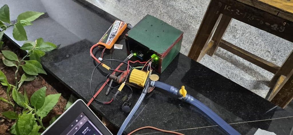
| 14 | 1/2″ Industrial Reinforced Braided PVC Hose & Ball Valve | VALVE1, HOSE | 1 Set | Plumbing loop with manual throttle valve to dynamically starve suction and induce cavitation |
| 15 | 15-Liter Graduated Water Reservoir Vessel | RES1 | 1 | Closed-loop hydraulic fluid supply basin |
Project Explanation Step by Step
1. The Industrial & Agricultural Crisis: Uncontrolled Cavitation
Centrifugal pumps are the lifeblood of agricultural tube-wells, rural borewell micro-irrigation, industrial cooling loops, and marine bilge systems. However, these pumps operate under hostile hydraulic conditions where static pressure at the impeller inlet frequently plummets below the saturation vapour pressure of the liquid (P < Pv).
In agricultural installations across rural regions, suction pressure collapses due to everyday field realities:
- Seasonally falling or fluctuating water tables: Dropping water levels increase suction lift height, starving the pump intake.
- Gradually clogged suction strainers / foot-valves: Silt, sand, and organic debris restrict inflow.
- Suction line air leaks: Weathered pipe joints allow air pocket ingress.
- Mismatched oversized pumps: High-discharge pumps installed on low-yield borewells quickly pull the water column down into continuous cavitation.
The Severe Economic Impact (Financial Justification for Farmers & Industry):
- Direct Equipment Loss: A standard 5 HP to 10 HP submersible agricultural pump costs ₹25,000 to ₹75,000. Replacing an eroded impeller and mechanical shaft seal assembly costs ₹8,000 to ₹15,000 per breakdown.
- Agricultural Crop Ruin: Unscheduled pump failures during peak 48-hour irrigation intervals inflict soil moisture stress in cash crops, triggering crop losses running into lakhs of rupees.
- High Return on Investment (ROI): Our clip-on AIoT retrofit unit costs under ₹3,500 (~$42) in BOM parts—paying for itself on day one by preventing even a single pump overhaul.
2. Fluid Dynamics: How Cavitation Destroys Impellers
According to Bernoulli’s principle, fluid accelerates through the pump suction eye, causing static pressure to drop to its lowest point. If the Net Positive Suction Head Available (NPSHa) drops below the Net Positive Suction Head Required (NPSHr), water spontaneously vaporizes into millions of micro-bubbles.
As these vapour bubbles are carried into the high-pressure volute region, they implode within 1 microsecond. Because the collapse is asymmetrical near the blade surface, high-velocity micro-jets slam into the metal with localized shockwave pressures exceeding 1 GPa (10,000 atmospheres) and temperatures exceeding 5,000 K. This micro-blast bombardment creates microscopic surface fractures, progressive metal pitting, loss of impeller mass, hydraulic head collapse, and severe dynamic unbalance.
3. Multi-Modal Non-Invasive Sensor Fusion Architecture
Traditional inline pressure sensors are invasive, requiring pipe drilling and causing leaks. Furthermore, vibration monitoring at low frequencies (< 5 kHz) gets drowned by motor hum, electrical hum, and normal turbulent flow.
Our unit straps directly onto existing pump casings using a high-temperature silicone clip-on mount, fusing three distinct sensory modalities:
- Dual Piezoelectric Vibration Pickups (PZ1 Suction, PZ2 Discharge): Piezoelectric ceramics exhibit broadband mechanical resonance. By monitoring both the suction eye and the discharge volute, the system isolates cavitation acoustic emissions from structural bearing rumble.
- Acoustic Microphone (MIC1): Captures the airborne ultrasonic “gravel crackle” emitted by collapsing vapour cavities.
- Low-Side Current Shunt (A2): Measures micro-ripples in motor armature current. When vapour bubbles collapse against impeller blades, instantaneous hydraulic torque fluctuates wildly, inducing detectable high-frequency current signatures.
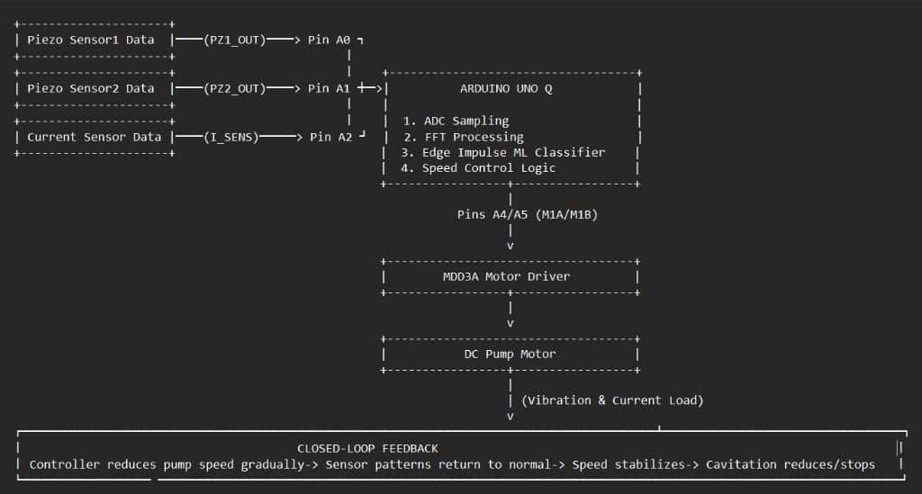
4. Dual-Core Asymmetric Processing Architecture
The core challenge in edge vibration analysis is handling continuous, jitter-free high-frequency sampling while executing machine learning inference and serving web telemetry. A single microcontroller cannot keep up, and a pure Linux microprocessor lacks real-time deterministic I/O.
Our design divides the computational workload across the dual-core architecture of the Arduino UNO Q:
- Real-Time STM32 Microcontroller Core (Zephyr RTOS): Executes continuous bare-metal 50,000 samples/sec (50 kHz) 14-bit ADC conversions across all three analog channels (A0, A1, A2). It buffers samples in triple 16,384-sample ring buffers and computes an onboard 4096-point Radix-2 FFT in hardware.
- Linux Microprocessor Core: Runs Debian Linux and connects to the MCU via the internal high-speed Arduino_RouterBridge. It fetches computed FFT spectra, extracts 20 band-power energy features across the 8 kHz – 20 kHz cavitation spectrum, runs an on-device Random Forest classifier, and serves the local SCADA HMI telemetry dashboard.
5. Autonomous “Sense → Decide → Act” Closed-Loop Feedback
Unlike conventional monitoring tools that merely trigger a passive warning buzzer, our unit provides an active closed-loop physical response:
- Sense: Dual piezo sensors, acoustic mic, and current shunt capture high-frequency signals at 50 kHz.
- Decide: The on-device Random Forest classifier evaluates the 8–20 kHz band-power vector every 100 ms, classifying pump state into Healthy (Nominal Flow), Incipient Cavitation, or Severe Cavitation.
- Act: If cavitation is detected, the adaptive PID controller immediately throttles the Cytron MDD3A PWM duty cycle (or adjusts a 0–10V VFD reference), reducing impeller speed by 15% to 25%.
- Restoration: Slowing the impeller reduces fluid velocity, raising static pressure above vapour pressure (P > Pv). Cavitation collapses vanish, sensor signatures normalize, and the system restores safe, steady-state water pumping without tripping or requiring manual intervention.
Coding Explanation and Configuration
1. High-Speed Bare-Metal Zephyr ADC & Onboard FFT (`Firmware/MCU_ADC_FFT/sketch.ino`)
To achieve the 50 kHz sampling rate required by the Nyquist criterion for 20 kHz cavitation detection, standard Arduino abstraction was replaced with direct Zephyr RTOS hardware configuration:
// Zephyr RTOS Fast ADC Configuration on STM32 Core
#include “Arduino_RouterBridge.h”
#include <zephyr/drivers/adc.h>
#include <zephyr/device.h>
#define BUFFER_SIZE 16384 // Triple parallel ring buffer size
#define SAMPLE_RATE 50000 // 50 kHz deterministic sampling (20 µs interval)
#define FFT_SIZE 4096
#define FFT_BINS (FFT_SIZE / 2 + 1)
#define DC_OFFSET 8192 // 14-bit midpoint bias
static const struct adc_channel_cfg ch_cfg_a0 = {
.gain = ADC_GAIN_1,
.reference = ADC_REF_INTERNAL,
.acquisition_time = ADC_ACQ_TIME(ADC_ACQ_TIME_TICKS, 5), // <0.5 µs conversion
.channel_id = 9, // Pin A0 Suction Piezo
};
Key Firmware Innovations:
- Pre-Calculated Twiddle & Hann Tables: A 4096-sample Hann window array and N/2 twiddle factor trigonometric arrays are precalculated in setup(), eliminating floating-point trig calls inside the time-critical loop.
- Decimation-in-Time Radix-2 FFT: Executes in under 12 milliseconds on the STM32, calculating exact spectral bin magnitudes in decibels (dB).
- Zero-Copy Inter-Core RPC: The MCU registers get_new_samples_synced, get_sample_count, get_fft_result, and get_fft_update_count via Bridge.provide_safe().
2. Linux Python Bridge & Data Acquisition Daemon (`Firmware/Edge_Service/main.py`)
The Python service polls the RouterBridge, extracts synchronized sample batches, and records microsecond-accurate CSV datasets:
# Linux Edge RPC Client & Batch Processing
from arduino.app_utils import Bridge
import numpy as np
# Poll synchronized 3-channel batches from STM32 ring buffer
payload = Bridge.call(“get_new_samples_synced”, 1024)
if payload and len(payload) > 0:
samples_a0 = payload[0::3] # Suction Piezo (A0)
samples_a1 = payload[1::3] # Discharge Piezo (A1)
samples_a2 = payload[2::3] # Motor Current (A2)
3. Feature Extraction & Machine Learning Classification
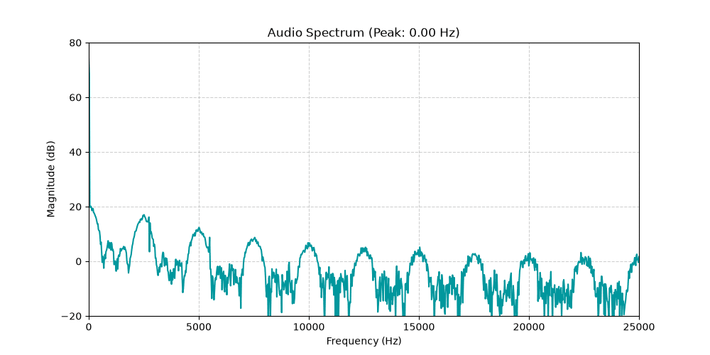
Bubble-collapse shockwaves emit high-frequency acoustic and structural vibration energy concentrated between 8,000 Hz and 20,000 Hz. Normal motor rotation and flow turbulence occur below 8,000 Hz.
| 89.44%AUDIO MODEL ACCURACY (ROC-AUC: 0.9795) | 87.50%PIEZO VIBRATION ACCURACY (ROC-AUC: 0.9623) |
Frames of 100 ms (5,000 samples at 50 kHz) are windowed, transformed via real FFT, and integrated into 20 linearly-spaced band-power energy bins across 8,000 Hz – 20,000 Hz (Δf = 600 Hz per band):
Energy[b] = Sum of |X[k]|2 for frequencies in band b (b = 1 to 20)
Separate regularized CART Random Forest models (criterion=’gini’, max_depth=12, min_samples_leaf=5, ccp_alpha=0.001) were trained and validated on independent recording holdouts:
| Evaluation Metric | Audio Classifier (Bubble Crackle) | Piezo Classifier (Casing Vibration + Current) |
|---|---|---|
| Testing Accuracy | 89.44% | 87.50% |
| Weighted Precision | 0.8993 | 0.9125 |
| Weighted Recall | 0.8944 | 0.8750 |
| Weighted F1-Score | 0.8948 | 0.8644 |
| Weighted ROC-AUC | 0.9795 | 0.9623 |
SCADA HMI Dashboard & Telemetry Architecture
A local SCADA HMI web application is hosted directly on the Linux SoC (port 3000), providing real-time telemetry gauges, an interactive P&ID pump schematic, and autonomous safety toggles.
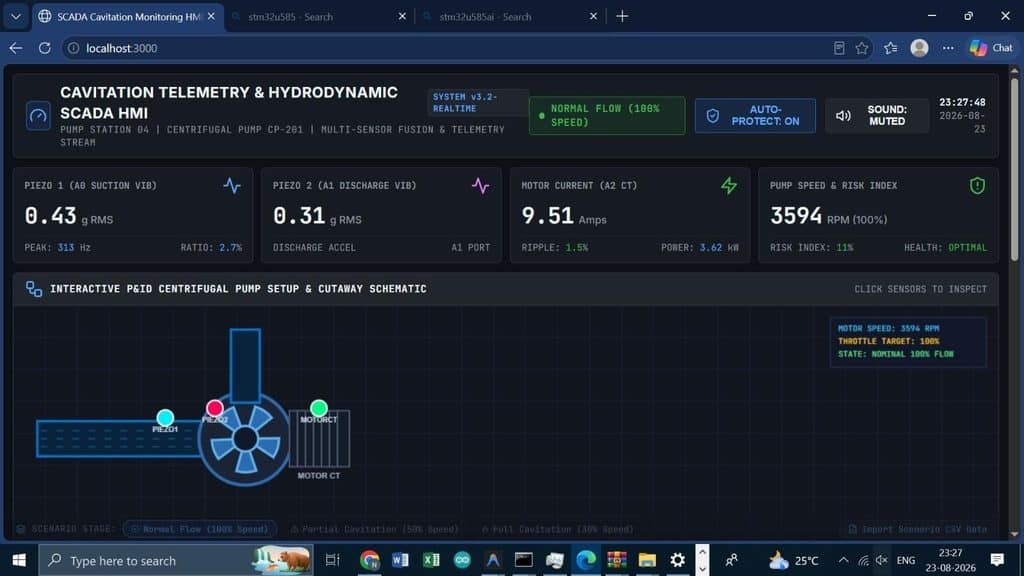
Dashboard Capabilities:
- Vibration Monitoring Tiles: Suction Vibration (Nominal: 0.43 gRMS), Discharge Vibration (Nominal: 0.31 gRMS).
- Motor Current Load Gauge: Continuously displays armature current (Nominal: 9.51 A) and tracks high-frequency ripple.
- Cavitation Risk Index (%): Empirically weights spectral energy in the 8–20 kHz band against the baseline, displaying a clear risk percentage (0–100%) and tri-color health state (Green = Optimal, Amber = Incipient Cavitation, Red = Severe Cavitation).
- Auto-Protection Mode Switch: When engaged, allows the closed-loop PID controller to autonomously govern PWM throttle.
Connection Explanation & Circuit Details
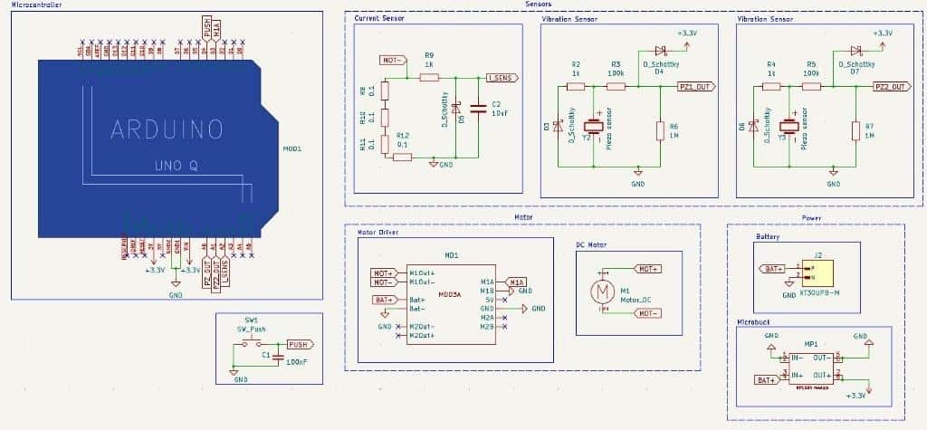
Hardware Circuit Protection Highlights:
- Piezoelectric Transient Clamping: Piezo discs generate high open-circuit voltage spikes when mechanically shocked. A 1 MΩ load resistor (R1, R5) drains baseline charge, a 100 kΩ series resistor (R2, R6) limits current, and antiparallel 1N5822 Schottky diodes (D1–D4) clamp analog lines strictly between -0.3 V and +3.6 V, protecting the STM32 ADC.
- Low-Side Current Shunt Network: Four 0.1 Ω 3W SMD resistors are connected in parallel (Req = 0.025 Ω) on the motor negative return line (MOT- to GND). Even at 10 A peak current, dissipation is only 2.5 W across a 12 W rated package. A 1 kΩ + 10 µF low-pass filter strips motor PWM commutation noise.
- Power Distribution & Star Grounding: The 3S 11.1V 4200 mAh LiPo battery powers the motor driver directly. The SmartElex MP1584 buck converter supplies regulated 5.0V to logic power. All grounds converge at a star-point ground to prevent motor inductive noise from coupling into the analog sensors.
| Subsystem | Component Interface | Microcontroller Pin | Signal Description |
|---|---|---|---|
| Vibration Sensor | PZ1 (Suction) Conditioning Node | Pin A0 (Zephyr Ch 9) | High-speed 50 kHz Suction Vibration Input |
| Vibration Sensor | PZ2 (Discharge) Conditioning Node | Pin A1 (Zephyr Ch 10) | High-speed 50 kHz Discharge Vibration Input |
| Current Sensor | Shunt RC Low-Pass Filter Out | Pin A2 (Zephyr Ch 11) | Motor Armature Current Load Signature |
| Motor Control | Cytron MDD3A M1A | Pin A4 (PWM) | Motor Forward / Speed Modulation Output |
| Motor Control | Cytron MDD3A M1B | Pin A5 (PWM) | Direction / Low-side Return Output |
| Power Input | MP1584 Buck Converter Out | 5V & GND | Regulated 5.0V Logic Power Rail |
Testing & Results
Step-by-Step Validation Protocol:
- Nominal Baseline Operation: The suction valve was fully opened (100% flow). The pump drew 9.5 A at 3,594 RPM. Vibration remained below 0.45 gRMS, and the Cavitation Risk Index registered a healthy 11%.
- Inducing Suction Starvation: The intake ball valve was gradually throttled, decreasing the Net Positive Suction Head Available (NPSHa) below NPSHr.
- Incipient Cavitation Detection: High-pitched crackling erupted, and the live FFT spectrum registered an immediate +18 dB energy surge in the 8–20 kHz band. Within 100 ms, the Random Forest model flagged Partial Cavitation, pushing the Risk Index to 68%. Under complete constriction, the system registered Severe Cavitation (>85%).
- Autonomous Adaptive Suppression: When Auto-Protection mode was activated, the closed-loop controller automatically dialed back the PWM duty cycle from 100% to 75% and then 60%. Lowering impeller speed raised local pressure above vapour pressure. Cavitation stopped instantly, vibration subsided to baseline (0.38 gRMS), and steady water discharge was maintained without damaging the pump.
State Progression During Physical Testing:
[Valve 100% Open] ─────────► [Healthy Flow: Risk Index 11%] ──► [Maintain 100% Throttle]
│
▼ (Suction Throttled)
[8–20 kHz Acoustic Surge] ──► [Partial Cavitation Flagged: Risk Index 68%]
│
▼
[Adaptive Controller Engages] ──► [PWM Trimmed to 75% -> 60%]
│
▼
[Vapour Cavities Suppressed] ──► [Sensor Signatures Normalize: Risk Index < 25%]
│
▼
[Stable Safe Water Delivery Maintained Without Pump Shutdown or Impeller Damage]
Full Experimental Hydraulic Testing video: click here
Source Code & Repository
The complete open-source project codebase, firmware, KiCad schematics, datasets, and machine learning pipelines are available in the public repository:
GitHub Repository: click here
Declaration
We confirm that this is our original work, developed by Team ElectroDynamix from the Manipal Institute of Technology (MAHE), Manipal. All team members have reviewed and approved this project submission.
