




AudioSense: An Offline Edge-AI Sound Awareness Device for the Deaf and Hard-of-Hearing is an assistive technology designed to improve environmental awareness and safety by converting important everyday sounds into recognizable vibration patterns and visual LED indicators. Developed on the Arduino UNO Q, the system detects sounds such as alarms, doorbells, knocks, clapping, and human calls, providing accessible alerts for people who are deaf or hard of hearing. Its offline architecture prioritizes privacy by processing audio locally without transmitting recordings to external servers.
The system distributes its workload across the board’s two processing domains. The STM32U585 real-time microcontroller samples the microphone and controls the vibration and LED alert mechanisms, while the Qualcomm QRB2210 Linux processor performs sound classification using an edge-AI pipeline. This division enables responsive alert generation while supporting more computationally intensive sound recognition. A key engineering achievement was identifying that microphone sampling had become limited to approximately 832 Hz by the Arduino loop dispatcher rather than the ADC hardware. The sampling implementation was subsequently optimized to achieve a measured rate of 16,000.13 Hz, with a 99th-percentile timing jitter of 1.25 microseconds, without relying on direct memory access (DMA).
By combining offline sound classification, real-time embedded processing, and multimodal alerts, AudioSense demonstrates a privacy-conscious approach to accessible sound awareness. The device aims to help users recognize important acoustic events in homes and other everyday environments without depending on continuous internet connectivity. Further testing across different acoustic environments, background-noise conditions, and user needs is essential to establish detection accuracy, response time, and practical reliability for safety-critical applications.
AudioSense listens for safety-critical sounds (an alarm, a doorbell or knock, someone clapping or calling out) and turns each one into a vibration pattern and an LED glyph that a deaf or hard-of-hearing user can feel and see. It runs on the Arduino UNO Q and splits the job across the board’s two processors: the STM32U585 samples the microphone and drives the alerts in real time, while the Qualcomm QRB2210 classifies sounds under Linux. No audio leaves the device. Along the way, a microphone sampling rate stuck at 832 Hz was traced to the Arduino loop dispatcher, not the ADC, and brought up to a measured 16,000.13 Hz with a p99 timing jitter of 1.25 µs, without using DMA.
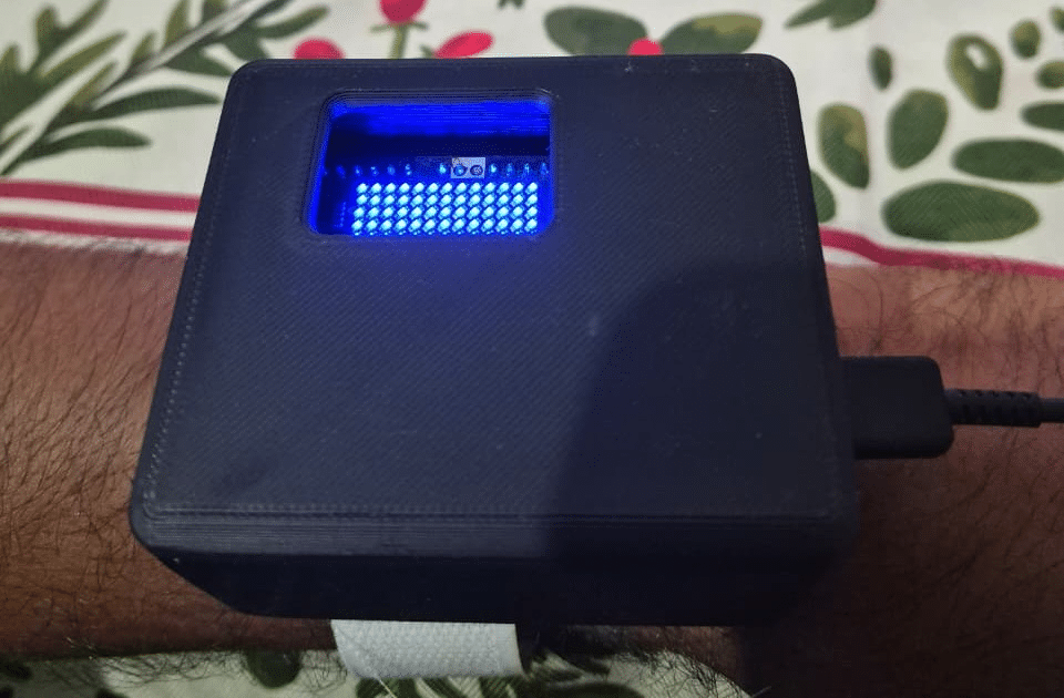
Component List
| ID | Name | Designator | Qty | Reference part / source |
| 1 | Arduino UNO Q (ABX00162): Qualcomm Dragonwing QRB2210 MPU + STM32U585 MCU, 2 GB LPDDR4 / 16 GB eMMC | MOD1 | 1 | Arduino ABX00162, stocked by DigiKey |
| 2 | MAX9814 electret microphone amplifier with AGC | MK1 | 1 | Adafruit 1713 (DigiKey 1528-1028-ND) or any MAX9814 module |
| 3 | DC vibration motor module with on-board MOSFET driver, 5 V | U1 | 1 | Generic coin-motor module, 3–5 V |
| 4 | Push button, acknowledge / silence alert | SW1 | 1 | Any momentary tactile switch |
| 5 | USB-C power supply or power bank, 5 V / 3 A | PS1 | 1 | Must support USB PD at 5 V / 3 A |
| 6 | USB-C data cable rated 5 V / 3 A | — | 1 | Data-capable; charge-only cables do not enumerate |
| 7 | Jumper wires and half-size breadboard | — | 1 set | — |
| 8 | 8×13 blue LED matrix | D1 | 1 | On the UNO Q board |
| 9 | Wi-Fi 5 / Bluetooth 5.1 radio | — | 1 | On the UNO Q board |
| 10 | Two-part 3D-printed enclosure with hook-and-loop wrist strap | ENC1 | 1 | Printed from Part1.STL and Part2.STL (see CAD model) |
No microSD card is required — the UNO Q carries 16 GB of onboard eMMC storage. No separate motor driver, relay or flyback diode is needed either, because the vibration motor module already integrates a MOSFET low-side switch.
Project Explanation Step By Step
The Problem
According to figures published under the Health Ministry’s National Programme for Prevention and Control of Deafness (NPPCD), about 63 million people in India, or 6.3% of the population, have significant hearing loss, and about 291 people per lakh have severe-to-profound loss. For them, a whole class of everyday information never arrives: the smoke alarm in the next room, the doorbell, the pressure-cooker whistle, a car horn behind them on the road, an infant crying, or somebody calling their name.
Existing alerting products serve India poorly. Dedicated sensor-transmitter systems are single-purpose and imported. AI-based home sound monitors depend on the cloud and are sold on subscription; one UK product costs roughly ₹9,000 up front plus an annual fee. Smartphone accessibility features work, but only while the phone is awake, unlocked and nearby, and they route ambient audio through a general-purpose OS.
AudioSense asks a narrower question: can one low-cost device recognise safety-critical sounds entirely on the device, with no cloud, no subscription and no audio leaving the hardware, and deliver the alert through channels a deaf user can actually perceive?
The Solution
AudioSense is a compact, always-listening node. It monitors ambient sound, classifies acoustic events on the device with a small trained classifier, and alerts the user through three non-auditory channels:
- Haptic — a distinct vibration pattern per sound class, so the user can tell a smoke alarm from a doorbell without looking at anything.
- Visual — a distinct glyph on the UNO Q’s onboard 8×13 LED matrix.
- Network — every event is logged to a web page served by the board over Wi-Fi, which any phone or laptop on the same network can open.
The system runs fully offline. Audio is processed in memory and discarded; nothing is recorded, stored or transmitted. Cloud-based alerting products cannot offer that, and working offline also removes the recurring fee that prices those products out of most Indian homes.
AudioSense is an assistive IoT device. It is not a medical device or a hearing aid, and it does not amplify sound. It converts selected sound events into touch and light.
Why the Arduino UNO Q — Using Both Brains
The UNO Q carries two very different processors on one board: a Qualcomm Dragonwing QRB2210 (quad-core Arm Cortex-A53 at 2.0 GHz) running Debian Linux, and an STMicroelectronics STM32U585 (Arm Cortex-M33 at up to 160 MHz) running Arduino sketches on the Zephyr RTOS. They talk through Bridge, Arduino’s RPC layer, which currently runs over a UART link (LPUART1 on the MCU side). That link comes up again under Known limitation, because its per-call latency is the main bottleneck in the current build.
AudioSense was designed specifically to exploit that split, because sound alerting has two requirements that pull in opposite directions. Classification wants a large model and floating-point maths; alerting wants hard, deterministic timing. Putting both on one processor forces a compromise. The UNO Q does not.
| Real-time brain — STM32U585 (Zephyr) | AI brain — QRB2210 (Debian Linux) | |
| Owns | Microphone sampling, DC-bias calibration, energy gate, ring buffer, LED-matrix glyphs, haptic PWM, acknowledge button | Feature extraction (log-mel / MFCC), classifier, decision smoothing, web UI, connectivity |
| Why it lives here | Deterministic timing. Alert latency must not depend on Linux scheduling jitter. | Memory and floating-point headroom for a real model that a small MCU cannot host. |
| Critical design rule | The glyph and vibration pattern tables are constants held on the MCU. Linux sends only a class index. | Never in the alert path. If Linux is busy, alerts still fire on time. |
This split is the key design decision. The MCU owns the entire alert path, so a detected event produces a vibration and a glyph with microcontroller timing even while the Linux side is loading a model or serving a web page.
How the System Works
- The MAX9814 microphone amplifier feeds an analogue audio signal, biased at approximately 1.25 V, into pin A0 of the UNO Q.
- At boot, the STM32U585 sketch averages a set of quiet samples to measure the true DC bias of the ADC input, then subtracts that bias from every subsequent reading. It also measures the ambient noise floor.
- The MCU samples A0 continuously into a circular buffer and runs a lightweight energy gate — a short-term RMS calculation against an adaptive threshold. This is deliberately cheap so it can run always-on.
- When the gate trips, the MCU captures a one-second window (including pre-trigger audio already sitting in the ring buffer) and sends it to the Linux side over Bridge.
- The Python application on the Linux side converts the window into log-mel and MFCC features and classifies it with the trained model.
- To suppress false alarms, a detection must win two out of three consecutive windows before it is confirmed. This voting step is the main tuning knob between responsiveness and false-positive rate.
- Linux returns a single class index to the MCU, which immediately fires the matching vibration pattern and LED glyph and logs the event to the web interface.
- The user presses the acknowledge button (or the button in the web UI) to silence the alert. Alerts also self-clear after a timeout.
Sound Classes and Alert Mapping
The contest build has four classes, and new classes can be added without changing the architecture. The haptic patterns differ in pulse count and length, because a user relying on touch alone has to tell alerts apart with the device out of sight:
| Class | Sound | Vibration pattern | LED glyph |
| 0 | Background / no event | None | Idle heartbeat |
| 1 | Alarm / beep | One long 400 ms buzz, repeating until acknowledged | Exclamation mark |
| 2 | Doorbell / knock | Three short 120 ms pulses | Bell |
| 3 | Name-call / clap | Two medium 250 ms pulses | Sound waves |
Coding Explanation and Configuration
Development Environment
All development is done in Arduino App Lab, the integrated environment that ships preinstalled on the UNO Q. App Lab is what makes the dual-brain workflow practical: a single project bundles the C++ sketch that runs on the STM32U585 under Zephyr, the Python application that runs on Debian, and the web UI, and it handles compilation and deployment to both processors together.
Two setup details cost real time if you get them wrong. First, use a USB-C data cable; with a charge-only cable the board never appears in App Lab. Second, power the board properly. The UNO Q negotiates a 5 V / 3 A USB Power Delivery contract, and an underpowered supply makes the Linux side brown out and reboot under load. A 1 A or 2 A phone charger is the most likely cause of unexplained resets on this board.
Project Structure
audiosense/
  app.yaml               bricks: [arduino:web_ui]
  requirements.txt       numpy (required), scikit-learn (optional)
  sketch/sketch.ino      sampling, energy gate, ring buffer, alerts, button
  python/
    main.py              bridge glue, 2-of-3 voting, modes, web API
    features.py          log-mel / MFCC in pure numpy
    classifier.py        scikit-learn MLP with numpy k-NN fallback
    dataset.py           raw sample storage and feature CSV
  assets/index.html      self-contained web UI
Dependency Choices That Matter
The feature extraction is about forty lines of pure numpy, with no librosa or scipy. That was a robustness decision: scipy has known installation failures on this platform, librosa pulls in numba, and a demo that cannot install its dependencies does not run. For the same reason the classifier tries a scikit-learn MLP first and falls back to a numpy k-nearest-neighbour implementation if scikit-learn is missing. On this board scikit-learn did not install, so the shipped build runs a distance-weighted k-NN. For four classes and a few dozen samples per class, that is an adequate model.
The Collect → Train → Run Workflow
AudioSense is trained on audio captured through its own microphone, in the room where it will be used. This matters far more than model architecture. A model trained on public datasets and deployed on a different microphone in a different acoustic environment will underperform a simple model trained on the real signal chain.
- Collect — switch the web UI to Collect mode and record 30 to 60 samples per class. Record background generously and first; it is the class that prevents everything else from false-firing. Vary distance, angle and loudness rather than recording the same sound repeatedly from one position.
- Train — press Train. The application extracts features, fits the classifier and reports whether it used the MLP or the k-NN fallback.
- Run — the system enters detection mode. A single transient shows as tentative; a repeating alarm or a knock confirms through the 2-of-3 vote and fires the alert.
The Test Alert buttons in the web UI fire each haptic pattern and glyph directly, with no sound and no model involved. That separates the alert hardware from the detection path, which helps both in debugging and in demonstrations.
Software visuals
The live analysis dashboard in Fig. 3 runs in the browser and shows what the device is hearing as it happens.
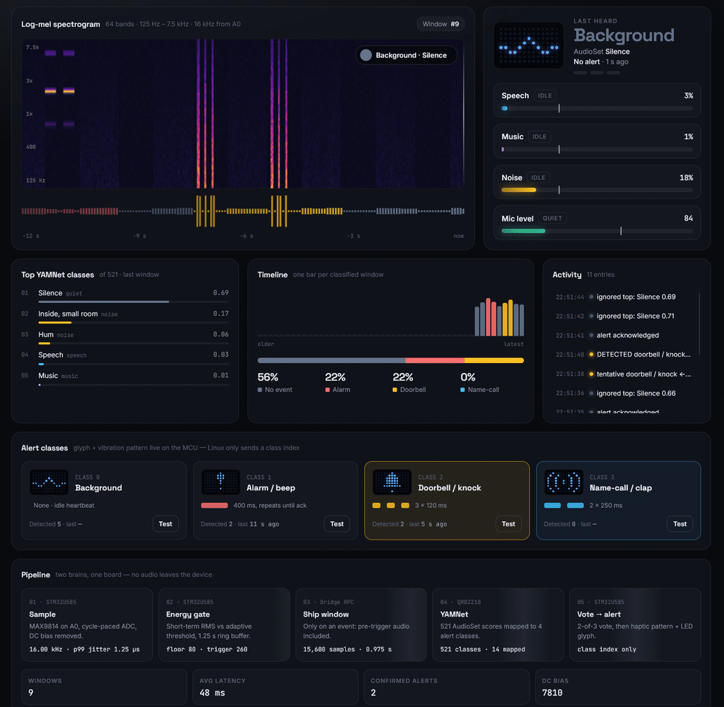
The top-left panel draws a 64-band log-mel spectrogram (125 Hz to 7.5 kHz, 16 kHz mono) of the last 12 seconds, with the raw waveform envelope underneath. To its right, the current top class is shown with its confidence (speech at 94% in this capture) and how long it has held, along with per-category meters for speech, music and noise. Each meter carries a marker at the detection threshold, which is set with the slider at the top of the screen together with a smoothing factor.
The middle row shows the five highest-scoring YAMNet classes out of 521, a timeline of the dominant class for every 0.48 s frame over the last 43 seconds (81% speech and 19% quiet in this run), and a time-stamped event log recording when speech started and when the room went quiet.
The pipeline strip along the bottom lists what runs every 0.48 s on the device. Audio is captured at 16 kHz mono as float32. A 0.975 s window (15,600 samples) slides forward by 0.48 s. Each window becomes a 96 × 64 log-mel patch using a 25 ms STFT window and a 10 ms hop. YAMNet, a MobileNetV1 depthwise-separable CNN with 3.7 million parameters and a 1024-dimensional embedding, scores the patch, and the 521 sigmoid outputs are grouped by the AudioSet ontology into speech, music and noise. Over this session the dashboard processed 162 frames at an average inference latency of 6.8 ms.
Engineering Deep Dive: Reaching a True 16 kHz Sampling Rate
The most instructive part of this build was not the machine learning. It was discovering that the microphone was being sampled at 832 Hz, understanding why, and fixing it. This section documents that investigation, because the result changes what the device is capable of and the method generalises to any Arduino-style sketch doing signal acquisition.
The Problem
The first working pipeline sampled at an effective rate of about 832 Hz. By the Nyquist–Shannon theorem, that limits the usable audio bandwidth to roughly 416 Hz. Broadband transients such as knocks and claps survive that, but human speech carries meaningful content up to around 8 kHz, and a 3 kHz alarm chirp is simply invisible. Recognising speech or high-pitched alarms requires sampling at 16 kHz.
Finding the Real Bottleneck
The intuitive explanation — that the Arduino analogRead() function is slow — turned out to be wrong, and measuring rather than assuming was what unlocked the fix. A dedicated probe application was built (leaving the main AudioSense app untouched) to time each layer of the stack:
A) analogRead() 37.31 us/call -> 26,806 Hz capable

A1) adc_channel_setup() 0.62 us/call

B) bare adc_read() 31.27 us/call -> 31,974 Hz capable

D) unpaced adc_read() -> 32,242 Hz ceiling

E) loop() iterations/sec 909.00 -> 1.10 ms per iteration
analogRead() costs 37 microseconds, not the milliseconds assumed — it is capable of nearly 27 kHz on its own, and the Arduino core wrapper adds only about 6 microseconds over a bare Zephyr adc_read(). The real culprit was line E. The sketch was taking one sample per loop() call, and the Arduino loop dispatcher on this core only runs at 909 Hz. The sampling rate was never limited by the ADC; it was limited by the loop.
The Fix — No DMA Required
The STM32U585 runs at 160 MHz. At 16 kHz that is 10,000 CPU cycles per sample for a conversion that takes about 31 microseconds. There is enormous headroom, so the fix is simply to stop sampling inside loop(): configure the ADC channel once at startup, then run a tight acquisition batch paced on the cycle counter using absolute deadlines, so timing errors cannot accumulate. Note that 62.5 microseconds is not an integer number of microseconds, so micros() cannot express the interval — pacing must be done on k_cycle_get_32() at the 160 MHz cycle clock.
F) cycle clock = 160000000 Hz, cycles/sample @16kHz = 10000

F) paced batch: 1600 samples in 100.00 ms -> achieved_hz = 16000.13

F) rate held at 16000.52 Hz over 999.97 ms

F) jitter: mean 0.20 us | p95, p99 <= 1.25 us | worst ever 16.96 us

F) zero samples exceeded half a sample period in any window
The result is an exact, non-drifting 16 kHz with 2× CPU headroom — 31 microseconds of work inside a 62.5 microsecond budget. Notably, no DMA was needed. Timer-triggered ADC with circular DMA is the textbook answer and would have been several days of register-level work against an undocumented core; measuring first showed it was unnecessary.
One constraint worth recording for anyone following this path: sketches on the UNO Q are LLEXT loadable extensions linked against a prebuilt Zephyr image, so Kconfig options and the devicetree cannot be changed from a sketch. The Zephyr sequenced-sampling path with interval_us also clamps to exactly 10 kHz on this core and cannot reach 16 kHz. The tight paced loop is the route that works.
Proving the Capture Is Real
A sample-rate counter reading 16000 proves nothing on its own: a broken loop re-reading a stale register would report the same number. The capture was therefore verified in the frequency domain. The table below gives the energy in each band, averaged over ten one-second windows per condition. All cells are in dB against one common reference, so the useful figure is the difference between a condition and silence in the same band, shown in the last two columns.
| Band | Silence (dB) | Talking (dB) | Whistle (dB) | Talking − silence | Whistle − silence |
| 0–250 Hz | 6.3 | 12.7 | 3.5 | +6.4 | −2.8 |
| 250–500 Hz | −2.8 | 15.5 | −7.1 | +18.3 | −4.3 |
| 500 Hz–1 kHz | −8.7 | 14.4 | −13.3 | +23.1 | −4.6 |
| 1–2 kHz | −11.1 | 15.2 | −12.1 | +26.3 | −1.0 |
| 2–4 kHz | −9.2 | 14.5 | 22.8 | +23.7 | +32.0 |
| 4–8 kHz | −7.1 | 11.5 | 1.5 | +18.6 | +8.6 |
In the 2–4 kHz band the whistle sits 32.0 dB above silence, with the dominant frequency resolved at 2854 Hz and holding between 2769 and 3013 Hz in nine of ten windows. A 2.85 kHz tone cannot be represented at the old 832 Hz rate, where Nyquist is 416 Hz, so this confirms real high-frequency capture and not just a fast counter. Speech agrees: talking raises every band by 6 to 26 dB, including 18.6 dB in the 4–8 kHz band where fricatives sit.
The whistle column also sits below silence in the four bands under 2 kHz (−1.0 to −4.6 dB). The most likely cause is the MAX9814’s AGC turning its gain down while a strong tone dominates the input, which pulls everything else down with it. In practice this means absolute levels from this front end are not calibrated sound pressure levels, and the classifier has to be trained on the AGC-shaped signal it will see in use. The collect-in-place workflow already does that.
The DC bias measured 6046 to 6052 counts on the 14-bit ADC. With the 3.3 V reference, 6049 / 16,383 × 3.3 V ≈ 1.218 V, close to the MAX9814’s nominal 1.25 V bias. The 6-count spread is about 1.2 mV (one LSB is 0.2 mV), so the analogue front end is quiet and behaving as designed.
Hardware Facts Confirmed from the Board
- A0 maps to PA4 on the STM32U585, on ADC1 channel 9, at 14-bit resolution.
- All Arduino analog pins A0–A5 are on ADC1, so the documented ADC1/ADC4 simultaneous-conversion erratum does not apply to this design.
- The ADC node carries zephyr,deferred-init, so the device is not ready until the first analogRead() initialises it.
- DMA support is present in the core (CONFIG_DMA_STM32U5) should a future revision need it, and the STM32 HAL/LL headers are reachable from the extension development kit.
Connection Explanation
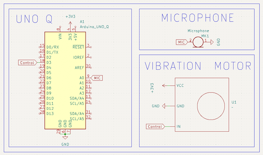
The wiring is deliberately minimal — three signal connections plus power. Everything else the project needs is already on the UNO Q board.
| Signal | From | To | Notes |
| Audio | MAX9814 OUT | A0 (PA4) | Analogue output biased at ~1.25 V, well inside the 3.3 V ADC range |
| Gain select | MAX9814 GAIN | VDD | Ties gain to 40 dB — a good default for room-scale ambient sound |
| Mic power | MAX9814 VCC / GND | 5 V / GND | Module accepts 3.3–5 V |
| Haptic | Vibration module IN | D3 (PWM) | Module has an onboard MOSFET, so the pin drives it directly |
| Motor power | Module VCC / GND | 5 V / GND | Module is 5 V rated; it also runs from 3V3 with reduced amplitude |
| Acknowledge | Push button | D2 to GND | Uses the MCU internal pull-up; active low |
Three points need explaining. The vibration motor must never be driven directly from a GPIO pin — the inrush current and inductive kickback will damage the microcontroller. The module used here avoids the problem because it integrates a MOSFET low-side switch and drive circuitry, which is why no relay, transistor or flyback diode appears in the bill of materials. A relay would in fact be the wrong component for this job: it offers no intensity or pattern control, switches audibly, and its own coil would still need a transistor to drive it.
Second, D3 drives the module with 3.3 V logic although the module is specified for 5 V logic. In practice a 3.3 V high turns on the module’s logic-level MOSFET reliably; if the vibration feels weak, add a level shifter.
Third, the MAX9814’s automatic gain control helps here. A doorbell across the room and a smoke alarm directly overhead differ enormously in level, and the AGC keeps both in a usable range instead of clipping the loud one or losing the quiet one. It also moves the noise floor around, which is why the energy gate uses an adaptive threshold and not a fixed one.
The signal levels also fit the ADC without extra parts. The MAX9814’s output swings at most 2 V peak-to-peak around its 1.25 V bias, so the signal stays between roughly 0.25 V and 2.25 V. That is inside the 0 to 3.3 V input range of the STM32U585’s ADC, so no divider or clamp is needed, even when the AGC is at full output.
Schematics
CAD Model
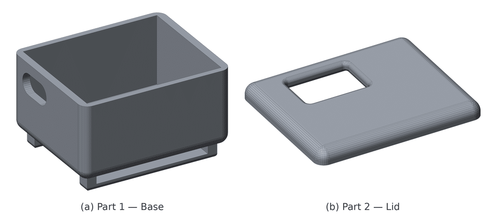
The AudioSense enclosure is a two-part 3D-printed case designed around the Arduino UNO Q, the MAX9814 microphone module and the vibration motor module, and sized to be worn on the wrist during testing. Both parts were exported as STL files (Part1.STL and Part2.STL) for printing.
Part 1 is the base, an open-topped shell measuring 80 × 66 × 48 mm with rounded vertical edges. A rounded slot in one side wall gives the USB-C cable access to the board, so the device can be powered and reprogrammed without opening the case. Two slotted rails on the underside take a hook-and-loop strap, which holds the unit on the wrist.
Part 2 is the lid, an 80 × 66 × 7 mm plate with filleted edges that closes the top of the base. A rectangular window with a filleted rim sits over the UNO Q’s onboard 8×13 LED matrix, so the alert glyphs stay visible with the case closed.
The case size is set by the UNO Q, which keeps the standard UNO outline of 68.6 × 53.4 mm. The base adds wall thickness and room for the microphone and motor modules on top of that, so making the device smaller needs a custom board; see Future work.
Testing
Bring the system up in stages. Each stage isolates one part of the chain, so a failure tells you exactly where the problem is rather than leaving you debugging the whole pipeline at once.
- Boot check — power the board and open the application log. Confirm the reported ADC sample rate and the calibration line showing the measured DC bias and noise floor. A bias of about 1.22 V (roughly 6,050 counts) confirms the microphone is powered and connected to A0.
- Microphone level — open the web UI and watch the level meter while talking and clapping. RMS should swing clearly above the trigger line while the noise floor stays low. This is where trigger_mult and min_trigger_rms are tuned.
- Alert hardware — press Test Alert for each class. This fires the haptics and glyphs with no sound and no model in the loop. Confirm all three vibration patterns are distinguishable by touch alone, with your eyes closed. If they are not, adjust the pattern timings; distinguishability is the entire point of the feature.
- Acknowledge — press the D2 button during an active alert and confirm it stops immediately.
- Capture path — clap, and confirm the log registers a captured event. This exercises the energy gate, the ring buffer and the MCU-to-Linux transfer together.
- Collect and train — record 30 to 60 samples per class, train, and check the reported model type and validation accuracy.
- Live detection — run the system and test each sound class from varying distances and angles. Then leave it running for an extended quiet period and count false positives. For a safety alerting device, false alarms are the failure mode that destroys user trust, so this measurement matters more than headline accuracy.
Before any of the software checks, a multimeter confirms the wiring with the board powered:
| Test point | Measure between | Expected |
| Microphone supply | MAX9814 VCC and GND | 5.0 V |
| Microphone bias, quiet room | MAX9814 OUT and GND | About 1.25 V DC (1.22 V measured through the ADC) |
| Acknowledge input | D2 and GND | 3.3 V idle, 0 V while pressed (internal pull-up) |
| Haptic drive | D3 and GND during Test Alert | Switches between 0 and 3.3 V in time with the pattern; a meter shows only the average, so use a scope or logic probe for timing |
| Supply under load | 5 V pin and GND while the motor runs | Stays near 5 V; a visible sag points to an undersized adapter |
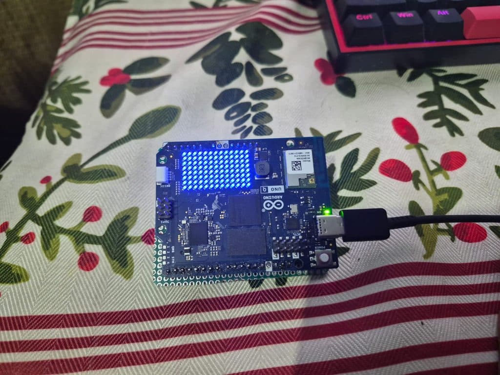
Results
| Metric | Target | Achieved |
| Sampling rate (acquisition path) | 16 kHz | 16,000.13 Hz measured, no drift over 1 s |
| Timing jitter | < half a sample period (31.25 µs) | Mean 0.20 µs; p99 ≤ 1.25 µs; worst case 16.96 µs |
| Verified audio bandwidth | > 2 kHz | 2854 Hz tone resolved 32 dB above silence |
| ADC DC bias | Stable, near 1.25 V | 1.218 V, within ±3 counts across all test windows |
| MCU → Linux transfer of a 1 s window | < 1 s | 4.76 s today (Bridge call latency; fix below) |
| Sound classes | 4, extensible | 4 implemented |
| Alert channels | 3 | Haptic, LED matrix, web page log |
| Audio leaving the device | None | None; fully offline |
Known Limitation and Next Steps
One measured constraint defines the next stage of the work. Moving a one-second window of 16 kHz audio from the MCU to the Linux side currently takes about 4.76 seconds: 32 KB sent as 63 chunks at roughly 75 ms per Bridge call. Profiling shows the cost is per-call round-trip latency and not bandwidth, since each call takes about the same time however small the payload.
That diagnosis points directly at the fix, and there is a clear ladder of options. Increasing the chunk size reduces the number of round trips proportionally — eight 4 KB chunks instead of sixty-three 512-byte chunks should bring the transfer close to 600 ms. Packing samples as int16 rather than as 32-bit integers halves the payload for free, since the ADC produces 14-bit data. Beyond that, computing MFCC features on the MCU and sending only the resulting feature vector reduces the transfer from 32 KB to roughly 2 KB. Because AudioSense is event-triggered rather than continuously streaming, a sub-second transfer sits comfortably within the target alert latency budget. Arduino has also said the SPI link between the two chips is meant for long bursts of data; once that path is exposed to sketches, it is the natural transport for raw audio windows.
The 16 kHz acquisition path itself is proven and stable; it is the inter-processor transport that is being optimised. The current demonstration build runs the complete detection and alerting pipeline end to end at a reduced sampling rate, which is sufficient for the broadband transient classes, while the 16 kHz path is integrated.
There is also no anti-aliasing filter ahead of the ADC. The MAX9814 passes audio well beyond 8 kHz, so content above the 8 kHz Nyquist limit can fold back into the band the classifier sees. The four current classes carry most of their energy below 4 kHz, but the next hardware revision should add a second-order low-pass filter with its corner near 7 kHz between OUT and A0.
Future Work
- Knowledge distillation — use a large pretrained audio model such as YAMNet as a teacher on a development machine to train a compact student network of roughly 150 KB, gaining accuracy without the memory cost of the full model.
- Expanded class library including India-specific sounds such as the pressure-cooker whistle, and regional name-call keyword spotting.
- Battery operation and a smaller body. The assembled case is about 80 × 66 × 55 mm because it is built around the UNO Q. A custom board carrying only the STM32U585, a MEMS microphone and the motor driver, running a distilled model on the MCU, would drop the Linux processor and most of the size and power budget with it.
- Integration as a safety feature within a neckband hearing assistance device, so a single wearable provides both amplification and sound-event awareness.
