




Falcon: An Open-Source Companion Robot for Assistive Communication and Caregiver Support is a socially interactive assistive robotics concept designed to help people with limited mobility communicate more easily, express their needs, and remain connected with caregivers, teachers, and family members. Inspired by the challenges faced by individuals with conditions such as amyotrophic lateral sclerosis (ALS), the project explores how an affordable, customizable companion robot can provide an accessible interface for requesting assistance, sharing messages, and facilitating everyday interactions.
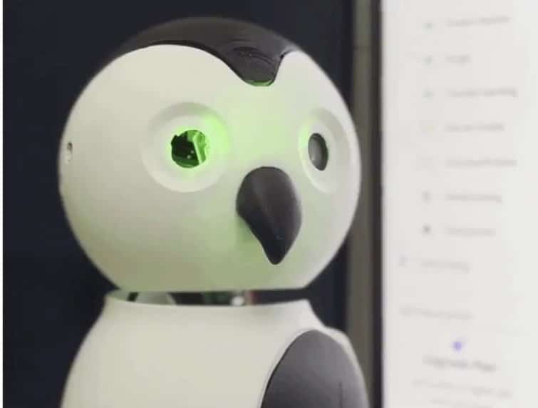
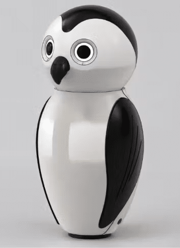
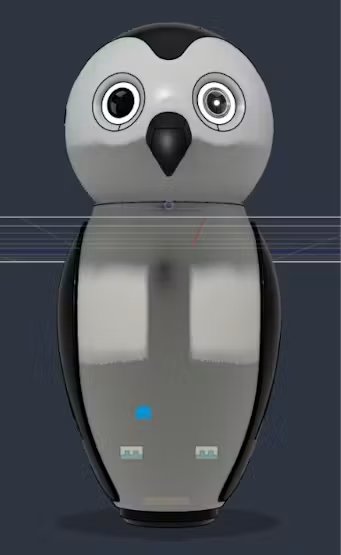
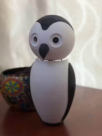
Designed with a distinctive falcon-inspired appearance, the robot combines physical interaction, visual feedback, limited movement, and camera-based environmental awareness. An onboard single-board computer (SBC) provides the processing and control capabilities needed to support its intelligent functions. RGB LEDs positioned near the eyes communicate visual states, a buzzer provides simple audible alerts, and a capacitive touch sensor on the head allows users to interact with the robot through touch. Servo motors enable head rotation and nodding, giving the robot expressive movements that can make interactions feel more natural. A camera-based system is intended to support environmental observation and potential emotion-related cues, while caregiver-facing monitoring and remote instruction features can help caregivers remain informed and interact with the user.
Project Members
| S. No. | Name | Role / Contribution |
|---|---|---|
| 1. | Robin Kanattu Thomas | Hardware, Firmware |
| 2. | Shravan Ramesh | Mechanical Design |
| 3. | Vidya Radhakrisnan | AI , Edge Impulse |
| . |
Component List:
| ID | Name | Designator | Quantity |
|---|---|---|---|
| 1 | Arduino UNO / Arduino Q | MOD1 | 1 |
| 4 | DFRobot Gravity: Digital Capacitive Touch Sensor For Arduino | RL1 . RL2 | 2 |
| 5 | SparkFun Electronics SparkFun RGB LED Breakout – WS2812B | F1 | 1 |
| 6 | Rechargeable Battery, Lithium Ion 7.4V ,1400mAh | BLE 1 | 1 |
| 7 | Tactile Switch, Top Actuated | LCD 1 | 1 |
| 8 | USB Expansion HUB, USB 2.0 Powered | S1 | 1 |
———————————————————————————————————
Project Explanation Step By Step :
Story
Hi fellow tinkerers.
It was always my idea to build a companion robot with its own character. A few months back I had an opportunity to visit a school here and saw a kid with ALS. For those who don’t know about ALS, it’s a motor neuron disease where muscular function gradually goes out. The great scientist Stephen Hawking had ALS. Coming home I kept on thinking. How can I make this kid more active, so he can communicate easily to caregivers and teachers, and also have a way to express his ideas really fast to everyone? And not just ALS, this could help anyone with limited mobility who struggles to call for help or make themselves heard.
Initial idea:
- Stephen Hawking had a computer connected to his wheelchair, and this can be something similar.
- Needs to be open-sourced, so anyone who wants to add features can add them.
- Instead of a computer on a wheelchair, what about a small-sized robot with limited motion and a camera?
- Should detect emotions and alert the caregivers.
- Caregivers can watch them as well and send instructions to the robot.
After that I thought a falcon would be an ideal look for creating a robot. It can use a buzzer to create limited sound, RGB LEDs near the eyes, and a small capacitive touch sensor on top of the head to pat the robot or just get its attention. It can have servos on the head to rotate and nod it. It can use an SBC for the controls and computation.Why falcon don’t know it will look good when it has a falcon look Why falcon? No strong reason. I just think it will look good with a falcon look.
Step 1: Let’s start
Let’s get all the components ready I will be using Arduino as SBC. First, we will test each component at a time, then we will connect everything together. We are using the Arduino UNO Q as the brain, and Arduino App Lab for coding it. There are two methods to code your Arduino UNO Q. One, connect the Arduino to a USB hub along with a monitor, mouse, and keyboard (SBC mode). Two, connect it directly to your computer (PC hosted mode). Open Arduino App Lab on your computer.
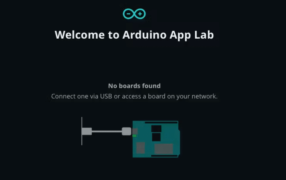
Connect your board and select Examples. You can find multiple examples inside this. You can select any example and test your Arduino UNO Q. I used the LED matrix example. Controlling the Arduino’s onboard LED matrix was amazing.
Step 2: Testing RGB LED with Arduino UNO Q
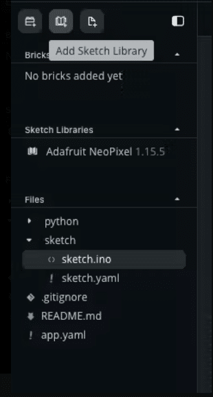
Go to Apps in Arduino App Lab. Select Apps, then create a new app. On the left side of the new app you can find Add Sketch Library. Search for the Adafruit NeoPixel library. We need this to control our RGB.
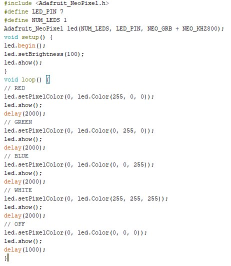
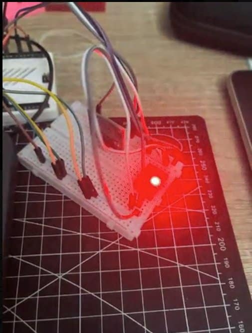
Inside the sketch.ino, put this code. I have used SparkFun’s WS2811 breakout board. Paste the below code and click Run in the top right corner of App Lab. The Fritzing diagram shows my connection to the RGB, but the problem is the image shows a different version of the RGB breakout board.Arduino –> WS2811Pin 7 –> D15V –> 5VGND –> GND
RGB LED Code
We will use this near the eyes of our robot, near the camera. Hope it glows well. Let’s check it after designing the external case of the robot.
We will use this near the eyes of our robot, near the camera. Hope it glows well. Let’s check it after designing the external case of the robot.
RGB LED is working separately; we will use two RGB LED for two eyes and different emotions will be shown using this.The RGB LED is working individually. We will use two RGB LEDs for the two eyes, and different emotions will be shown using this. So we need to test it together with the whole system.
Note: The RGB LED was taking too much power, so it’s ideal to connect it to an additional battery source. Connect the power pins, 5V and GND, to the battery’s power and GND. Also connect the GND of the Arduino to the GND of the battery (use a breadboard for easier connection).
Step 3: We will test the Servos
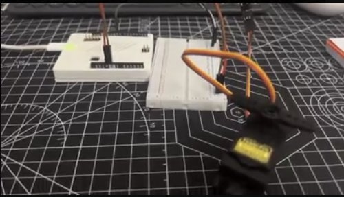
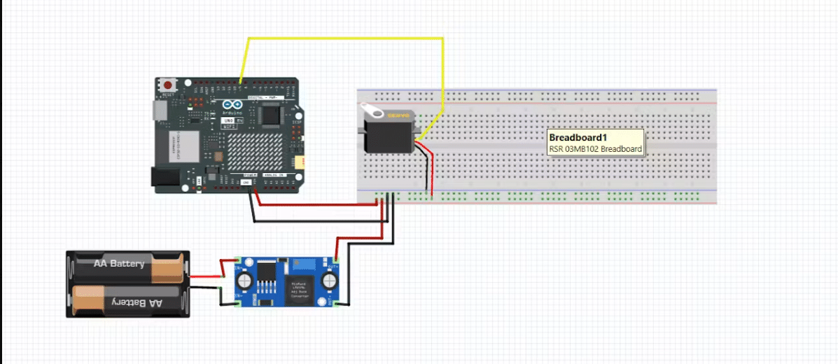
Our plan is to use two servos for nodding and rotation of the robot’s head. We will test the servo first. Connecting a servo is relatively easy. Here in this project I have used MG995 servos. The signal pin has to connect to a PWM pin of the Arduino. Since this is not a digital signal, the Arduino uses PWM to control the servo. Those who want to read more can use PWM can use this link. Since one servo motor won’t take too much power, I am connecting it directly to the Arduino. But you can connect it with a battery as well, as we have done above with the RGB LED.
Battery power –> servo redBattery GND –> servo brownArduino pin 9 –> servo orangeArduino GND –> battery GND
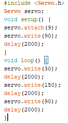
Now in App Lab, create a new app. Then go to Add Sketch Library, same as how we added a library in the previous step, but here we will search for Servo. Download it, then copy and paste the below code and click Run.
Step 4: Connecting two servos with a capacitive touch sensor.
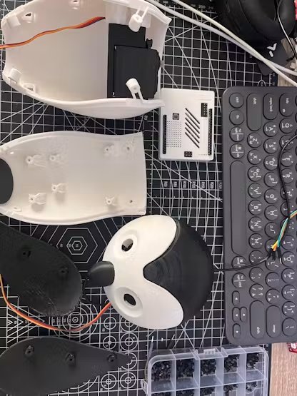
Now I have printed two enclosures for testing the motors, the nod and rotating functions. The initial idea was to use the same file when the entire robotic enclosure was ready, but this design was bulky. So this is the latest version of the servo mechanism I have used. It is in the attachment area, the STL file.
The first servo is for rotating the head and it’s attached to pin 9, and the nod servo to pin 3.
Battery power –> rotating servo redBattery GND –> rotating servo brownBattery power –> nodding servo redBattery GND –> nodding servo brownArduino pin 9 –> rotating servo orangeArduino pin 3 –> nodding servo orangeArduino GND –> battery GNDCapacitor GND –> Arduino GNDCapacitor VCC –> Arduino VCCTouch pin 2 –> capacitor IO
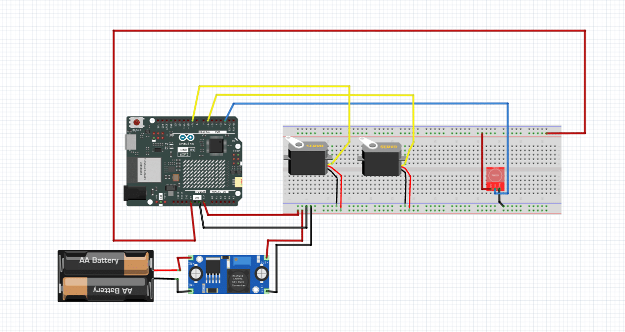
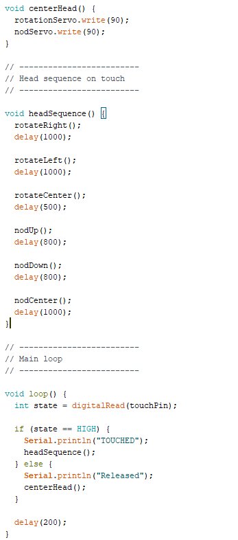
Note: I have added my own functions like nodUp() and other head functions. We can use this later in our project.
Step 5: Buzzer and falcon sound.
For this project I have used a buzzer. This robot looks like a bird and it won’t create a lot of different sounds, so a buzzer is enough. Connecting a buzzer to the Arduino is simple, like connecting an LED. But making it sound like a falcon was the difficult part. I used some references from the internet, wanted to create some functions, and with some trial and error it sounds like a falcon, I guess. I had created some functions with different sounds.
Arduino pin 12 –> buzzer +Arduino GND –> buzzer –
Note: In this I have added a capacitive touch to make a random sound, but the Fritzing diagram doesn’t show this.
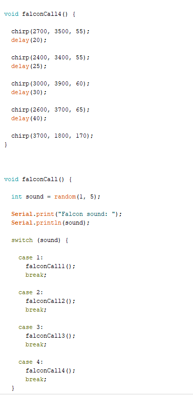
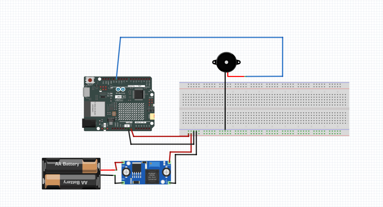
For coding this buzzer I have used Arduino App Lab’s agent mode. On the lower right side, beside the WiFi icon, there is a button for agent mode.
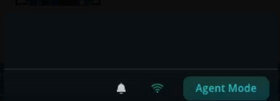
It is in lower part of Arduino App Lab.
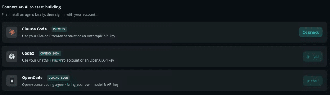
I have used Claude Code
This was the feature I always dreamed about. An Arduino UNO coded and debugged with an AI agent. Since different buzzer and falcon sounds were difficult to create.
Fig 5. Testing the device with both the app interface and the touch display.
Step 6: Edge Impulse emotion analysis custom model.
Arduino App Lab helps to connect a custom model.
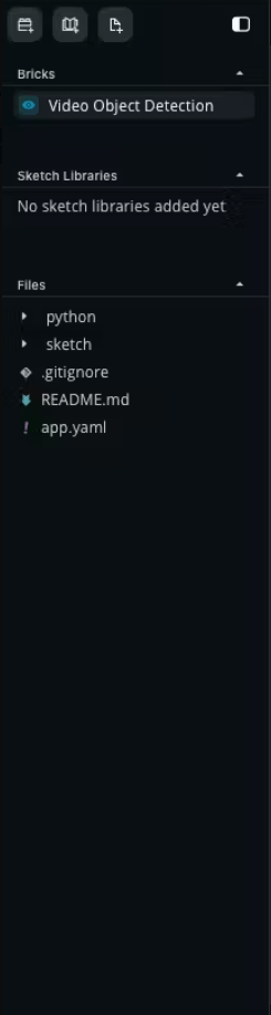
- Inside the left sidebar, click on Add Bricks.
- Since our model is video image classification, I have added that brick.
- You can go to these tutorial links from Arduino and Edge Impulse for how to do this.
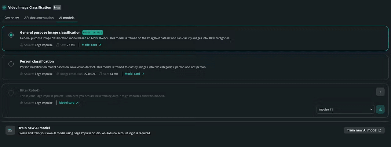
Inside that you can find Train New AI Model. For this you need an Arduino login and an Edge Impulse sign in. After that I have used Edge Impulse to train a model.
I primarily used a dataset from this link, about a paper which had a facial dataset for children: https://data.mendeley.com/datasets/b33pf78h62/1 . I started collecting data from multiple data sources too like Kaggle to train our Edge Impulse model to detect emotions like:
- anger
- Fear
- joy
- natural
- surprise
- unknown: Uploading the images is the first step
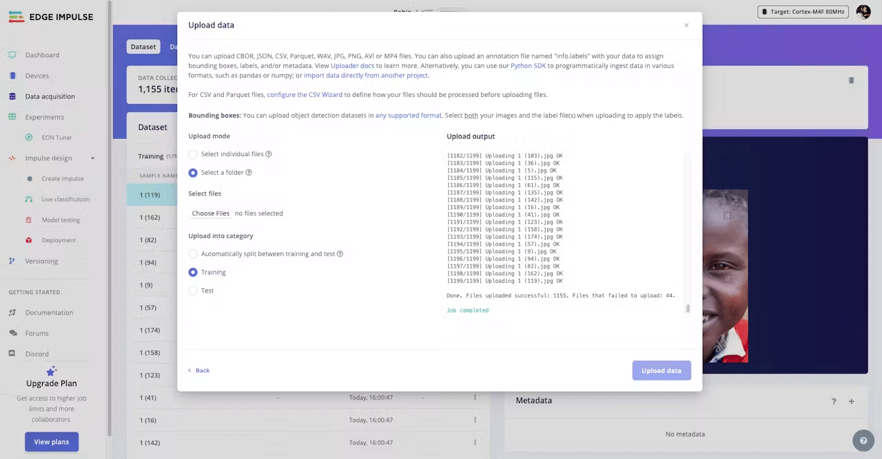
- Labelling the images for different emotions.
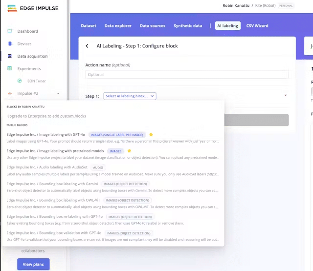
- Edge Impulse offers an AI labelling option, but my issue was with the bounding box labelling using Gemini. I used the Gemini API, but the available model was Gemini 2.5 and it was creating an error.
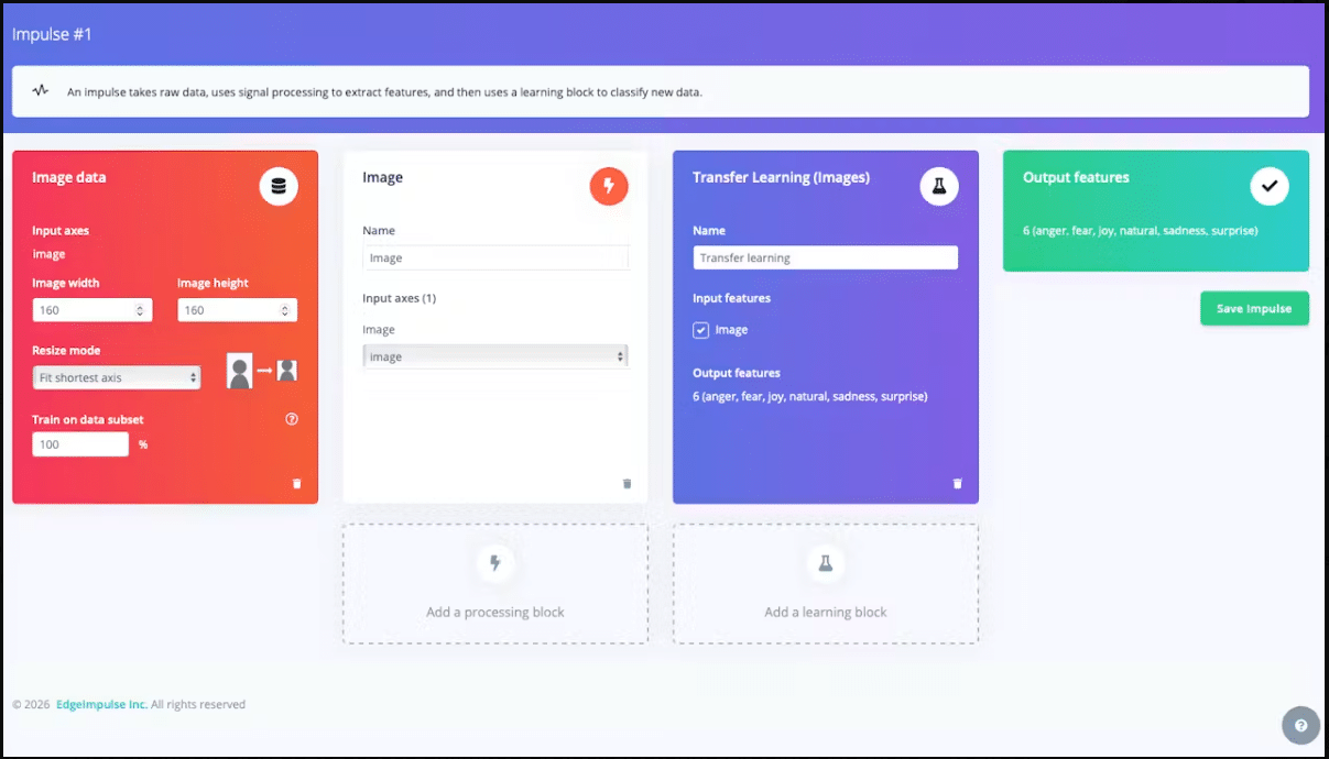
This is the impulse I created.
Image data block:
- Image width 160, image height 160
- Resize mode: Fit shortest axis
- Train on data subset: 100%
Processing block: Image
Learning block: Transfer Learning (Images), named Transfer learning, with Image as the input feature.
Output features: 6 classes (anger, fear, joy, natural, unknown, surprise).
Then click Save Impulse.
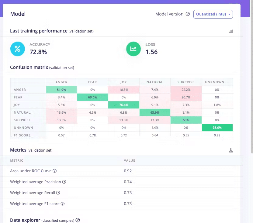
After training, these were my results.Accuracy: 72.8%Loss: 1.56
Is this good? It’s not perfect. Accuracy is 72.8%, and some emotions like anger and surprise are weak because these expressions look similar and the model confuses them. Joy, fear, and natural came out better. Even I find it difficult to understand these emotions. 😮
It can. be still improved.
- Add more images for the weak classes, especially anger and surprise.
- Keep the number of images balanced across all emotions.
- Clean the labels so each image is clearly the right emotion.
- Retrain and check the confusion matrix again.
After training, go to Model testing in the left sidebar. This runs your model on test data it has never seen, which shows how it really performs. Set the expected outcome for each sample, then click Classify all.
My result was 50.54% accuracy.
After this, you can find the custom model in AI Models inside the Bricks
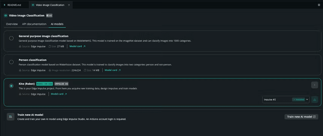
Note: This is a first version, trained on a limited dataset, so it is not perfect. The accuracy will improve as I add more and better data. For now it works well enough to show the idea and test the robot, but it is an assistive helper, not something to fully rely on.
In App Lab, create a new app and add two bricks: Video Image Classification (run our model) and WebUI – HTML (the web page). Inside the Video Image Classification brick, open the AI models tab and select our trained model.
Note: our model is image classification, not object detection, so use the Video Image Classification brick. Do not add both, they clash on the camera port.
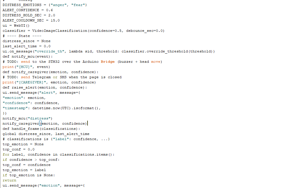
The backend (main.py) reads the top emotion each frame, shows it on the page, and raises an alert when a distress emotion holds for two seconds. Distress is set to anger and fear.
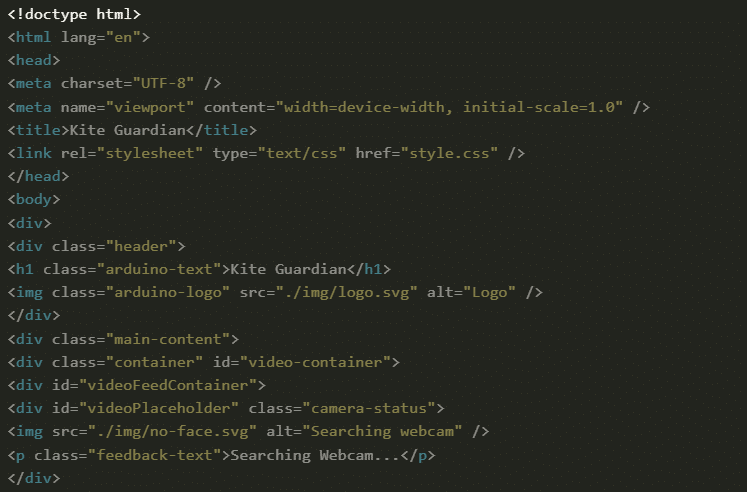
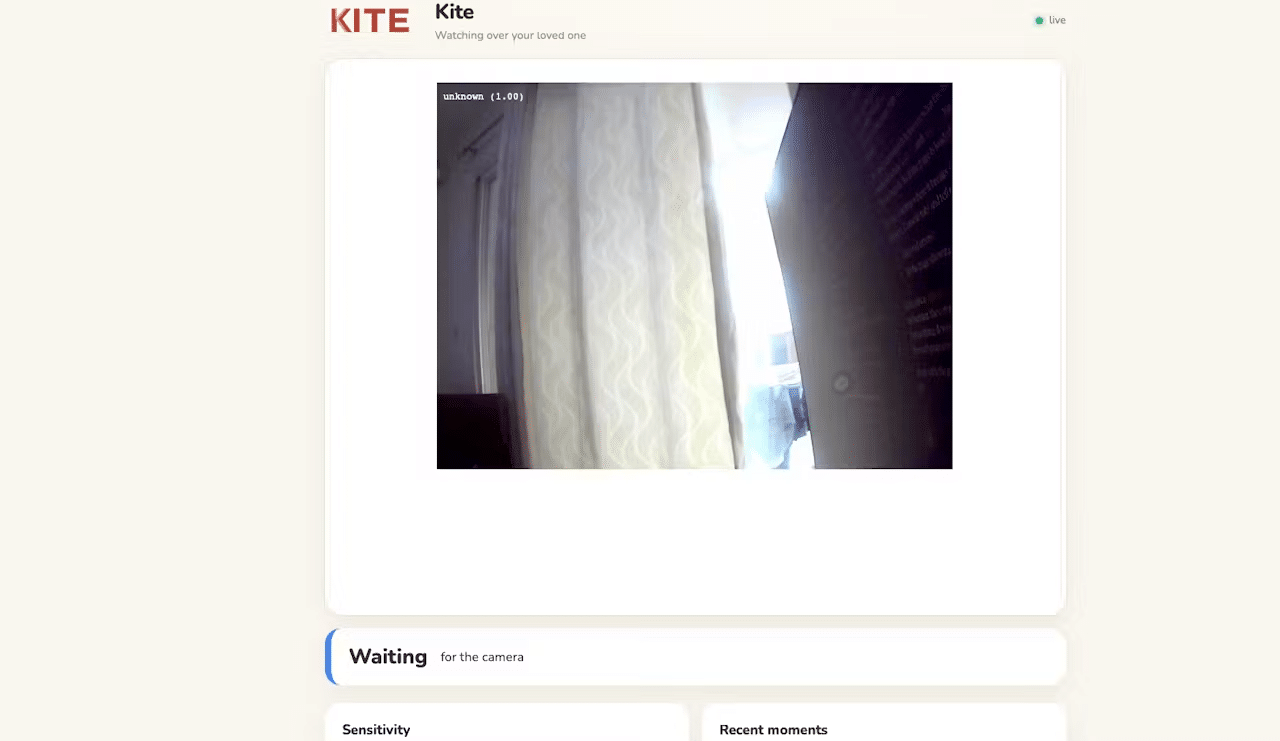
The frontend (index.html and app.js) shows the live video, current emotion, a red banner and beep on distress, and recent emotions.
Connect the camera and hub, click Run, and open your board address in the browser, for example http://192.1xx.0.xxx:7000. Hold an angry or fearful face for two seconds to test the alert.
Make sure you add WebUI – HTML inside the bricks.
Here is the public version of the model: https://studio.edgeimpulse.com/public/1106415/live
Now let me try Telegram, and connect the LED to turn red on distress, blue normally, and green on joy. Then we connect everything together.
Now let me create a Telegram bot to send messages. We need two things first.
Bot token. In Telegram, message @BotFather, send /newbot, follow the prompts, and it gives you a token that looks like 123456789:ABC….
Chat ID. Message your new bot once (say hi), then fetch your chat ID.
You can check this pdf link for assembly: kite assembly guide.pdf
Last steps :now lets connect everything together and test it.
Find the complete code in the attachment. Make sure you have added the libraries. This is the final wiring diagram.
Schematics
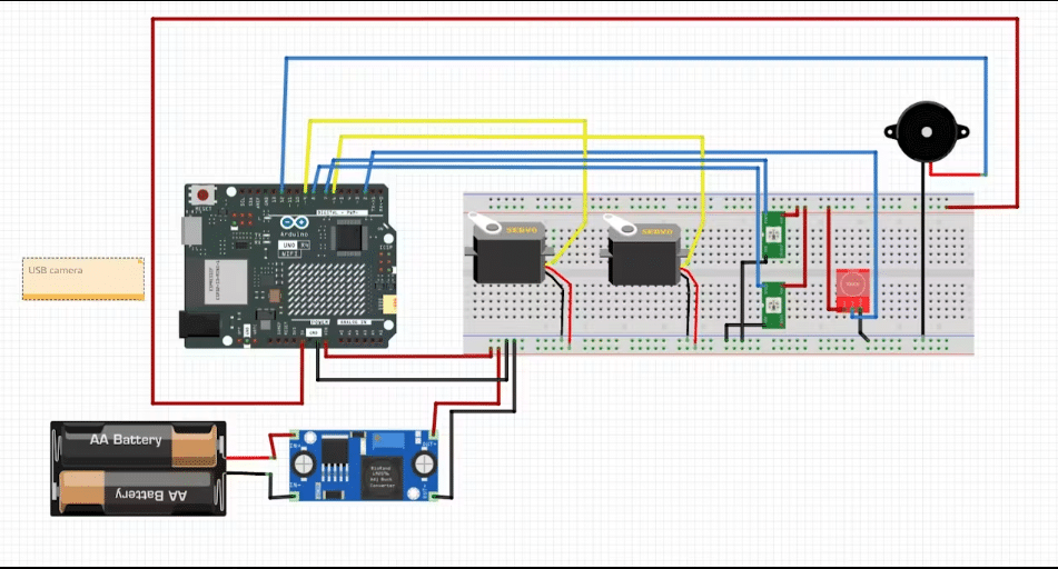
This project can be more. It will be an ongoing project until I give it to the kid and see his reaction. I will build a mobile app, use a better camera module, and optimise the detection. I will keep you updated. Till then, happy hacking!!!
GitHub Code: click here
CAD File: click here
