Fauna Flash: An AI Wildlife-Crossing Alert System for Forest Roads Using Arduino UNO Q is a solar-powered edge-AI safety system designed to reduce wildlife–vehicle collisions on roads passing through forest habitats, including known animal-crossing corridors in Kerala’s Malayattoor Forest Division. Conventional static warning signs often fail to attract drivers’ attention, particularly when visibility is poor or motorists become accustomed to seeing the same signs. Fauna Flash addresses this limitation by detecting wildlife in real time and activating a dynamic roadside warning display to alert approaching drivers.
The detection unit combines a USB camera with an Arduino UNO Q, using a YOLO-based object-detection model on its Linux processor to identify elephants locally without requiring cloud services or an internet connection. When an elephant is detected, the UNO Q communicates with a XIAO nRF52840, which transmits a compact, one-character alert through a REYAX RYLR998 LoRa link. A separate solar-powered roadside alert post receives the message using an Arduino Nano and activates a bright P10 RGB LED matrix displaying an elephant-warning symbol. This distributed architecture separates wildlife detection from driver notification, enabling alerts to be transmitted over a long-range, low-power wireless link.
By integrating local AI inference, LoRa communication, and solar-powered warning infrastructure, Fauna Flash aims to provide a practical and energy-conscious approach to wildlife-crossing safety in areas with limited connectivity. The system is designed to support earlier driver awareness and encourage speed reduction when elephants approach or enter a monitored crossing zone. Field validation is required to assess detection accuracy, communication reliability, alert latency, solar-energy availability, and performance under varying lighting and weather conditions. The prototype is intended to supplement existing road-safety measures rather than replace speed controls, wildlife corridors, or other established conservation practices.
Video: Fauna Flash – AI Wildlife Crossing Alert (Arduino UNO Q)
Team Members
| S. No. | Name | Role |
| 1 | Madhav | Concept, hardware design, AI model, firmware and field testing |
| 2 | Kalyani B | Documentation and power subsystem |
Problem Statement
Roads through forest areas, such as those crossing the Malayattoor Forest Division in Kerala, cut straight through the paths that elephants and other animals use every day. The only warning drivers get is a static signboard. Most of these boards are faded or rusty, and because they are always there, drivers learn to ignore them. At 60 km/h a driver has only about 1.5 seconds to react when an animal steps into the headlights. The result is collisions, injuries, damaged vehicles and the loss of protected wildlife.

Solution
Fauna Flash turns a static forest road into a live safety corridor. A solar-powered detection node is mounted along a known crossing corridor. It uses a USB camera and an Arduino UNO Q that runs a YOLO-Pro object-detection model locally on its Linux processor, with no cloud or internet needed. When an elephant is detected, the UNO Q signals a XIAO nRF52840, which sends a one-character alert over a REYAX RYLR998 LoRa link. A solar-powered alert post at the roadside receives the alert on an Arduino Nano and lights up a bright P10 RGB LED matrix with an elephant warning symbol, giving drivers the extra seconds they need to slow down.
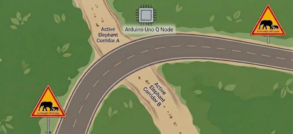
Component List:
| ID | Name | Designator | Quantity |
| 1 | Arduino UNO Q | MOD1 | 1 |
| 2 | USB camera (Logitech webcam) | CAM1 | 1 |
| 3 | Seeed Studio XIAO nRF52840 Sense | MOD2 | 1 |
| 4 | REYAX RYLR998 LoRa transceiver | LORA1, LORA2 | 2 |
| 5 | 433 MHz helical antenna | ANT1, ANT2 | 2 |
| 6 | Arduino Nano R3 | MOD3 | 1 |
| 7 | 5 V relay module | RL1 | 1 |
| 8 | P10 RGB LED matrix panel | DISP1, DISP2 | 2 |
| 9 | HD-WF1 LED control card | MOD4 | 1 |
| 10 | 5 V 20 A power supply (LED driver) | PS1 | 1 |
| 11 | 20 W solar panel (node) | SP1 | 1 |
| 12 | 55 W solar panel (post) | SP2 | 1 |
| 13 | Solar charge controller (HW-632 / XH-M603) | CC1 | 1 |
| 14 | Solar charge controller (Luminous, post) | CC2 | 1 |
| 15 | 18650 Li-ion cell + 4S BMS | BAT1, BMS1 | 4 + 1 |
| 16 | 12 V 32 Ah lead-acid battery (post) | BAT2 | 1 |
| 17 | XL4015 5 A DC-DC buck converter | U1, U2 | 2 |
| 18 | Zero PCB, wire grommets, enclosures, misc. | ENC | ~ |
Project Explanation Step By Step :
The system has three parts: the detection node in the forest, the LoRa link, and the solar alert post at the road. The signal path is:
Camera → UNO Q (YOLO-Pro on Linux MPU) → STM32 pin D0 HIGH → XIAO nRF52840 pin D2 → RYLR998 (AT+SEND “H”) ⇢ RYLR998 → Arduino Nano → D13 → relay → HD-WF1 → P10 LED matrix
Step 1: Train the Detection Model
The dataset was built from images of wild elephants in South Indian forest backgrounds, labelled in Roboflow and trained as a YOLO-Pro object-detection model in Edge Impulse (2 classes, 83/17 train/test split). The model reached about 83% accuracy in field tests.
1. Collect and label images in Roboflow, then export the dataset.
2. Import it into an Edge Impulse object-detection project and train with YOLO-Pro.
3. Deploy the trained model to the Arduino UNO Q so it can be used by the Video Object Detection brick in Arduino App Lab.
Step 2: Program the Arduino UNO Q (Detection Node)
The UNO Q has two processors: a Qualcomm QRB2210 running Debian Linux, and an STM32U585 microcontroller. The Linux side runs the camera and the model; the MCU side drives the output pin. The two talk over the Arduino Router Bridge. Create a new app in Arduino App Lab, add the Video Object Detection and WebUI bricks, and plug the USB camera into the UNO Q.
Python (Linux MPU): every frame’s detections are sent to the web dashboard. When an elephant is seen with more than 85% confidence, the script calls set_led on the MCU, but only when the state changes:
# uno_q.py (Linux MPU)
ui = WebUI()
detection_stream = VideoObjectDetection(confidence=0.5, debounce_sec=0.0) current_led_state = -1 def process_detections(detections: dict):
global current_led_state
elephant_detected = False for label, values in detections.items():
for value in values:
confidence = value.get("confidence", 0.0)
ui.send_message("detection", message={"content": label,
"confidence": confidence}) if "elephant" in label.lower() and confidence > 0.85:
elephant_detected = True target_state = 1 if elephant_detected else 0
if target_state != current_led_state:
Bridge.call("set_led", target_state)
current_led_state = target_state detection_stream.on_detect_all(process_detections) App.run()
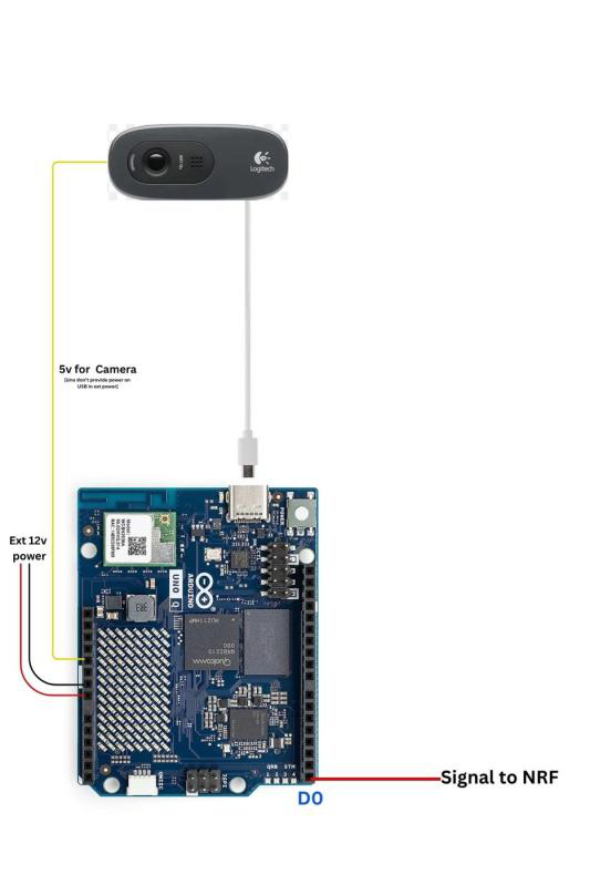
Sketch (STM32 MCU): set_led pulls D0 HIGH (3.3 V) for 15 seconds and lights the onboard LED. D0 is the trigger line to the XIAO.
// stm.ino (STM32 MCU)
const int ledPin = LED_BUILTIN;
const int outputPin = D0; // 3.3 V trigger to XIAO D2 void set_led(int state) {
if (state > 0) {
digitalWrite(ledPin, LOW); // LED on (active-low) digitalWrite(outputPin, HIGH);
delay(15000); // hold alert for 15 s } else {
digitalWrite(ledPin, HIGH);
digitalWrite(outputPin, LOW);
}
} void setup() {
pinMode(ledPin, OUTPUT);
pinMode(outputPin, OUTPUT);
Bridge.begin();
Bridge.provide("set_led", set_led);
} void loop() {
Bridge.update();
}
Note: the UNO Q did not start the camera in USB host mode when running only from the battery, so the camera gets its own 5 V feed (see Fig 10).
Step 3: Build the LoRa Transmitter (XIAO nRF52840 + RYLR998)
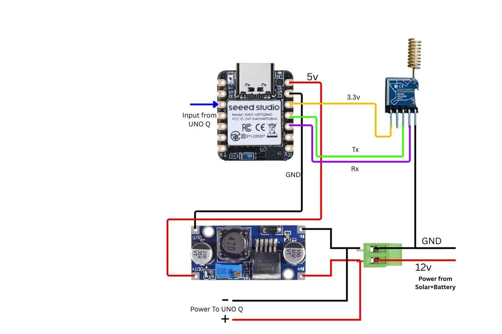
The RYLR998 is a sub-GHz LoRa module controlled with simple AT commands over UART. It runs on 3.3 V only. Solder the XIAO and the RYLR998 onto a zero PCB and wire them as below (see Fig 11):
| From | To | Purpose |
| UNO Q D0 | XIAO D2 | Detection trigger (input, pull-down) |
| UNO Q GND | XIAO GND | Common ground |
| XIAO D10 (TX) | RYLR998 RXD | UART to LoRa |
| XIAO D9 (RX) | RYLR998 TXD | UART from LoRa |
| XIAO 3V3 / GND | RYLR998 VDD / GND | LoRa power |
| Buck 5 V | XIAO 5V | Board power |
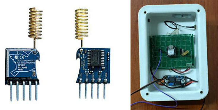
Fig 3. RYLR998 LoRa module (left) and the XIAO + RYLR998 transmitter board on zero PCB (right)
The sketch sets the module address and network ID, then sends “H” whenever D2 is HIGH:
// Nrf.ino  (XIAO nRF52840 transmitter)
#define LORA_RX_PIN 9
#define LORA_TX_PIN 10
#define INPUT_PIN   2
SoftwareSerial loraSerial(LORA_RX_PIN, LORA_TX_PIN);
void setup() {
 loraSerial.begin(115200);
 pinMode(INPUT_PIN, INPUT_PULLDOWN);
 delay(1000);
 loraSerial.print("AT+ADDRESS=0\r\n");
 delay(500);
 loraSerial.print("AT+NETWORKID=10\r\n");
 delay(500);
}
void loop() {
 if (digitalRead(INPUT_PIN) == HIGH) {
		 loraSerial.print("AT+SEND=0,1,H\r\n");   // addr 0, 1 byte, "H"		 delay(250);
 }
 delay(50);
}
Step 4: Power and Assemble the Detection Node
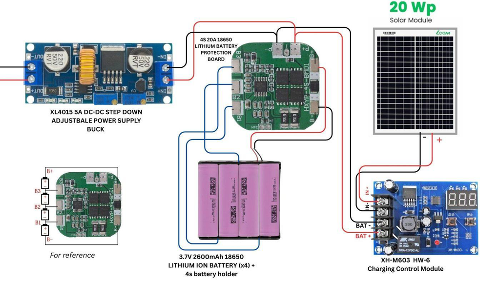
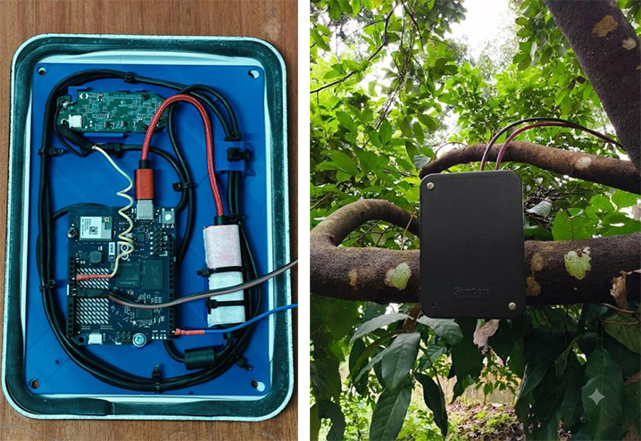
The node runs off-grid. A 20 W solar panel charges a 4S 18650 Li-ion pack (14.8 V nominal) through a charge controller and 4S BMS. An XL4015 buck converter steps the pack down to 5 V for the XIAO and the camera (see Fig 13). Place the UNO Q, transmitter board and wiring in a weatherproof enclosure with cable grommets, and mount it on a tree facing the elephant corridor.
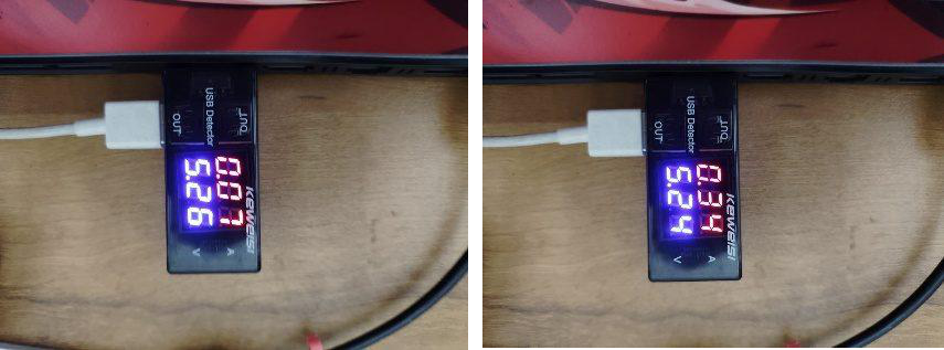
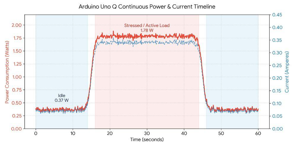
Measured on a USB power meter, the UNO Q draws about 0.37 W at idle and 1.78 W while running inference
:
Step 5: Build the Receiver (Arduino Nano + RYLR998)
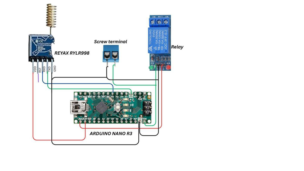
Inside the alert post, a second RYLR998 connects to the Arduino Nano: LoRa TXD to D4, LoRa RXD to D5, VDD to 3.3 V. The RYLR998 uses 3.3 V logic, so use a level shifter or resistor divider on the Nano TX line. D13 drives a 5 V relay that triggers the HD-WF1 display card (see Fig 12). Both modules must use the same address (0) and network ID (10).
The Nano parses each +RCV=<addr>,<len>,<data>,<RSSI>,<SNR> line. On “H” it holds D13 HIGH for 5 seconds; the timer restarts with every new packet, so the warning stays on while the elephant is in view:
// Nano.ino (Arduino Nano receiver)
// Packet format: +RCV=<addr>,<len>,<data>,<RSSI>,<SNR>
int firstComma = receivedData.indexOf(',');
int secondComma = receivedData.indexOf(',', firstComma + 1);
int thirdComma = receivedData.indexOf(',', secondComma + 1);
String actualData = receivedData.substring(secondComma + 1, thirdComma); actualData.trim(); if (actualData.equals("H")) {
digitalWrite(OUTPUT_PIN, HIGH); // trigger relay -> HD-WF1 outputPinHighStartTime = millis();
isOutputPinTimedHigh = true;
} // Release after HIGH_DURATION_MS (5 s) with no new packet if (isOutputPinTimedHigh &&
millis() - outputPinHighStartTime >= HIGH_DURATION_MS) { digitalWrite(OUTPUT_PIN, LOW);
isOutputPinTimedHigh = false;
}
Step 6: Build the Solar Alert Post
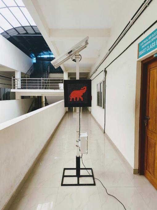
Two P10 RGB LED matrix panels are driven by an HD-WF1 control card, which stores the pre-loaded elephant warning symbol and shows it when the relay triggers it. A 5 V 20 A supply powers the panels.
The post runs from a 55 W solar panel and a 12 V 32 Ah lead-acid battery through a solar charge controller, so it keeps working at night and in cloudy weather. Mount the receiver box, battery and control electronics on the pole below the display.
Testing
Power the node and the post, then check that the App Lab web dashboard shows live detections. Show the camera an elephant image. The UNO Q LED should light, the XIAO serial monitor should print “Sending ‘H'”, and within moments the post should display the elephant symbol. The display clears 5 seconds after the last alert.
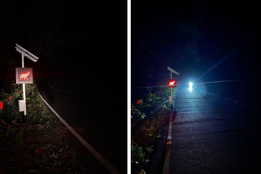
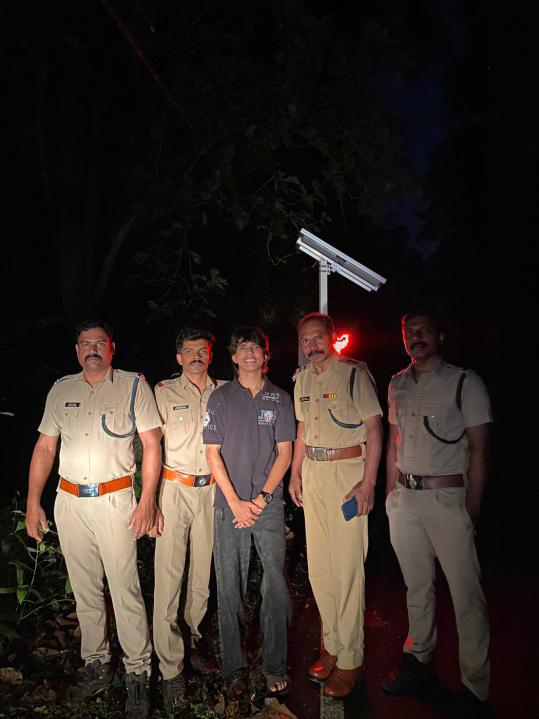
Field testing was done with permission from, and together with, the Malayattoor Forest Division on the Vadattupara road near Edamalayar, a known elephant hotspot. Drivers noticed the bright dynamic warning straight away and slowed down well before the danger zone. Forest officers helped choose the corridors where detection nodes should go.
Schematics