




Jal Rakshak is Inspired by the urgent need for a proactive, localized defense network, Jal-Rakshak is an autonomous, decentralized Edge AIoT Water Security System split into a two-tier monitoring and diagnostic pipeline:
Tier 1: Distributed Pipeline Edge Nodes: Low-power sensor nodes are retrofitted along municipal pipelines at 10km intervals. Running localized TinyML models, these nodes continuously analyze acoustic pipe vibrations alongside physical telemetry (pH, TDS). They detect subterranean pinhole leaks and sewage ingress at the source, transmitting pre-processed, long-range health alerts across a robust LoRa mesh network that bypasses unreliable cellular grids.
Tier 2: Handheld AI Forensic Terminal (Master Gateway): Powered by the Arduino Uno Q, this serves as a mobile command center and a rapid \point-and-shoot\” diagnostic tool. It features an integrated optical \”Testing Cup\” assembly. When a worker samples water on-site
Component List
Bill of Materials on DigiKey: click here
| ID | Name | Quantity | Designator |
|---|---|---|---|
| 1 | Arduino UNO / Arduino Q (4GB RAM, 32GB eMMC) | 1 | MOD1 |
| 2 | Arduino UNO Q (2GB RAM, 16GB eMMC) | 1 | MOD2 |
| 3 | LoRa RF Transceiver Module (RA-01S) | 2 | MOD3, MOD4 |
| 4 | USB-C Multiport Hub | 2 | HUB1, HUB2 |
| 5 | 16MP Autofocus USB Camera Module (B0561) | 1 | CAM1 |
| 6 | 6V 2W Solar Panel (ETFE) | 2 | PV1, PV2 |
| 7 | 18650 Li-Ion Cell 3.7V 2.5Ah | 10 | BT1–BT10 |
| 8 | MQ-136 H2S Gas Sensor Module | 1 | SENS1 |
| 9 | MQ-135 Air Quality Sensor Module | 1 | SENS2 |
| 10 | Resistor 20kΩ 1% 1/4W Axial | 10 | R1–R10 |
| 11 | Resistor 10kΩ 5% 1/4W Axial | 10 | R11–R20 |
| 12 | USB Type-C to Type-C Cable | 2 | CBL1, CBL2 |
| 13 | Mini USB Microphone | 1 | MIC1 |
| 14 | Boost Voltage Regulator IC 1A (PAM2401) | 3 | U1–U3 |
| 15 | Waterproof DS18B20 Temperature Probe | 1 | SENS3 |
| 16 | 5V Magnetic Buzzer | 1 | BZ1 |
| 17 | Turbidity Sensor (TSW-10) | 1 | SENS4 |
| 18 | RS485 Modbus pH Water Sensor Kit (SEN0708) | 1 | SENS5 |
| 19 | Gravity Analog TDS Sensor / Meter (SEN0244) | 1 | SENS6 |
| 20 | Jumper Wires M-to-F 6″ (28 AWG) | 40 | JMP1–JMP40 |
| 21 | General Purpose Prototyping Breadboard PCB | 1 | PCB1 |
| 22 | Flush Cutter Shears 5.13″ | 1 | TOOL1 |
| 23 | Double-Sided VHB Foam Tape (1/4″ × 5yd) | 1 | MISC1 |
———————————————————————————————————
Project Explanation Step By Step :
1. The Story: Inspiration from Two Tragedies in India’s Cleanest City
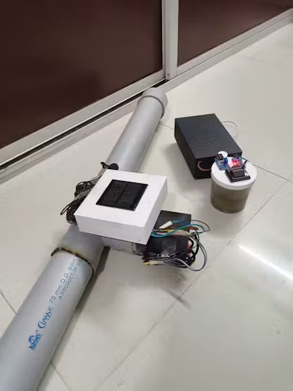
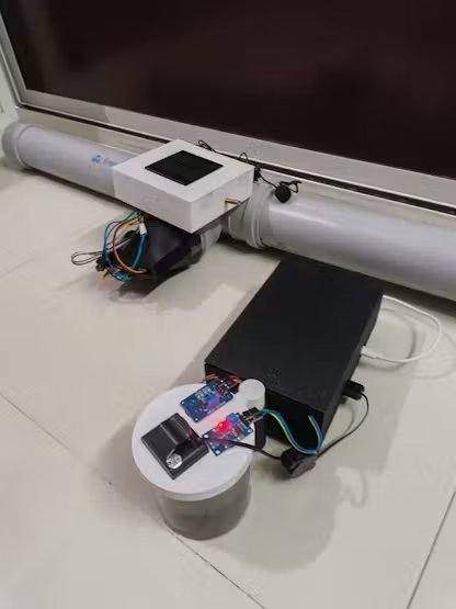
For eight consecutive years, Indore has proudly held the crown of India’s cleanest city. But beneath our sweeping, spotless avenues lies an invisible, aging, and unmonitored infrastructure. Between December 2025 and mid-2026, two catastrophic infrastructural failures fractured our city, claiming innocent lives and turning a basic human necessity—water—into a tool of terror and displacement.
As a resident of Indore, I could not sit idly by. This is the story of why Jal Rakshak had to be built.
Tragedy 1: The Silent Poisoning of Bhagirathpura (December 2025 – January 2026)

What happens when the water meant to sustain life carries a death sentence? In late December 2025, a public health nightmare unfolded in the congested neighborhood of Bhagirathpura, Indore.
- The Contamination: A public toilet line was tragically constructed directly above a decaying, 40-year-old municipal drinking water pipeline. When the water supply cycled off, a localized vacuum (negative pressure) sucked raw sewage directly into the dry drinking water main.
- The Human Toll: Over 2, 800 residents were struck down by excruciating vomiting, diarrhoea, and severe dehydration. Hospitals were overwhelmed as emergency wards overflowed.
- The Heartbreak: While official state records confirmed 22 deaths, local communities and media tracking reported over 30 lives cut short by E. coli and Vibrio cholerae. Mothers lost children, and families buried breadwinners—all because they drank the water flowing from their own kitchen taps.
- The Information Blindspot: Residents had complained about foul-smelling, discolored water for days. However, because municipal testing was manual, sporadic, and confined only to distant treatment plants, the warning signs were ignored until the bodies piled up.
Tragedy 2: The Bherughat Pipeline Catastrophe
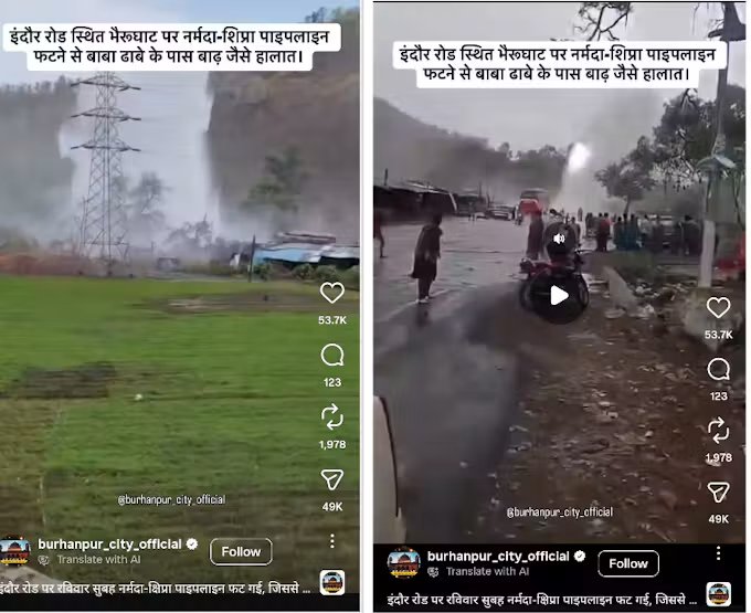
While Bhagirathpura suffered in silence, the structural vulnerability of Indore’s water grid exploded into public view on the Indore-Khandwa Road near Bherughat.
- The Blast: Months of unaddressed structural wear and ignored leak complaints culminated in a massive, explosive blast on the high-pressure Narmada-Kshipra Link Pipeline.
- The Chaos: The violent rupture unleashed a terrifying 150-foot water fountain blasting into the sky, tearing into overhead high-tension power lines, and creating an immediate electrocution hazard.
- The Destruction: Millions of gallons of precious, treated water were instantly vaporized or wasted. The resulting flash flood submerged adjacent properties, ruined businesses, and physically washed away local homes, leaving vulnerable families displaced.
- The Crippling Aftermath: The blast completely paralyzed the primary water lifeline for Indore, Mhow, and Rau, plunging hundreds of thousands of citizens into an acute water crisis and sparking intense civic backlash against systemic negligence.
The Common Denominator: A Broken, Blind Network
Both disasters stem from the exact same systemic failure: Our municipal corporation is flying blind.
- They cannot see the microscopic sewage seeping into underground fractures.
- They cannot see the critical pressure spikes that lead to catastrophic pipeline explosions.
2. The Solution: Jal Rakshak (The Shield of Indore)
I engineered Jal Rakshak (Water Protector) not as a mere science project, but as a real-time, digital defensive shield for the Indore Municipal Corporation (IMC). It transitions our city from a reactive, blind management style to an automated, proactive defense system.
Jal Rakshak deployed a network of smart Pipe Nodes at critical municipal junctions, feeding data continuously into a centralised Master NodeGateway to prevent both types of tragedies:
- Preventing Another Bhagirathpura: Our Pipe Nodes utilise continuous multi-parametric sensing (Turbidity & TDS). The moment raw sewage crosses into a water line, the node detects the structural change in water quality within 30 seconds. It immediately broadcasts an emergency flag, allowing the IMC to isolate the contaminated zone before a single citizen takes a drink.
- Preventing Another Bherughat Blast: By integrating continuous acoustic transducer, Jal Rakshak actively listen the internal stress of main pipelines. A sudden abnormal pressure spike sound triggers an automatic relief alert. Pinpointing the exact coordinates of a leak so engineers can patch it before it mutates into a 150-foot explosion.
- Designed for the Real World: Knowing that Indore’s pipes are buried deep under concrete and soil, standard Wi-Fi or cellular networks fail. Jal Rakshak uses low-frequency LoRa (Long Range) wireless communication, cutting through soil and dense urban clutter to reach the Master Gateway up to 10km away without needing expensive cellular SIM cards at every node.
- Empowering the IMC:The Master Gateway feeds directly into a cloud-based dashboard. If a node flags a breach, the system is designed to trigger alert to officers and a web portal to alert the people, allows officers to instantly choking off the danger area while preserving water security for the rest of the ward.
System Architecture
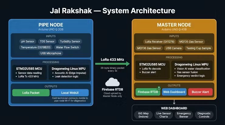
This architecture outlines a comprehensive end-to-end water monitoring system, transforming raw physical sensor data into actionable insights on a centralised web portal. The workflow is split between localised sensing at the pipe, a long-range communication network, a localised secondary testing station, and a cloud-based presentation layer.
1. Two-Tier Node Ecosystem: The architecture splits operations between field-deployed Pipe Nodes (monitoring pipeline distribution) and a central Master Node (supervisory control and laboratory-grade forensic testing)
2. Acoustic Edge AI & Multi-Sensor Pipe Monitoring: Each Pipe Node combines physical water probes (pH, TDS, turbidity, temperature, flow) with a USB microphone running a local Edge Impulse TinyML model to detect pressurised pipe leaks in real time directly on the pipeline.
3. Resilient Long-Range LoRa Telemetry (433 MHz): Field nodes operate completely offline, packing telemetry into a tiny 29-byte binary packet transmitted every 3 seconds over LoRa (433 MHz) to easily penetrate soil and underground chambers without needing cellular connectivity.
4. Dual-Brain Processing on Arduino UNO Q: Both the Pipe and Master nodes leverage the UNO Q’s dual-processor architecture—the STM32U585 MCU manages microsecond sensor reads, interrupts, and LoRa timing, while the Qualcomm Dragonwing Linux MPU handles compute-heavy AI inference and web servers.
5. Forensic Water Testing Station on Master Node: In addition to receiving pipeline data, the Master Node features an automated sample cup equipped with a Vision AI camera (detecting visible impurities) and gas sensors (MQ135 for NH3, MQ136 for H2S) to verify sewage contamination and sound audible buzzer alarms.
6. Single Cloud Gateway & Interactive Web Dashboard: The Master Node acts as the sole internet gateway, securely streaming synchronised network data to Firebase RTDB while hosting a centralised Web Dashboard featuring Indore GIS mapping, live sensor trend charts, and instant emergency alerts.
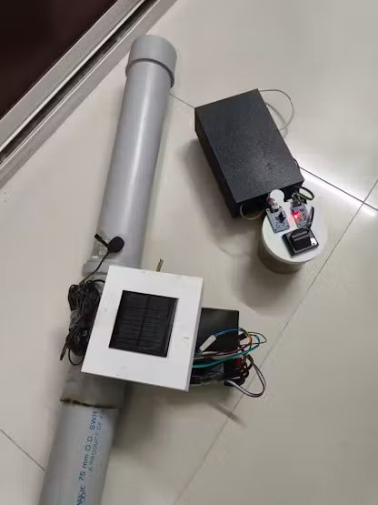
3. Building the Pipe Node
The Pipe Node is the frontline of the Jal Rakshak network. To function reliably in the harsh, subterranean environments of municipal distribution lines, the nodes require a rugged, waterproof physical footprint combined with ultra-low-power, intelligent edge processing. This section details the complete engineering lifecycle of the node, from raw schematic to a deployed, Edge AI-powered device.
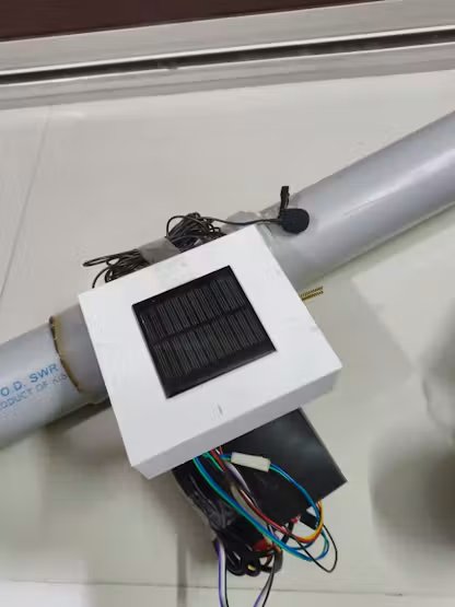
Part A: Hardware Fabrication & Assembly for Pipe Node
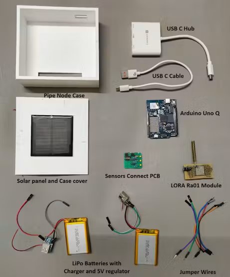
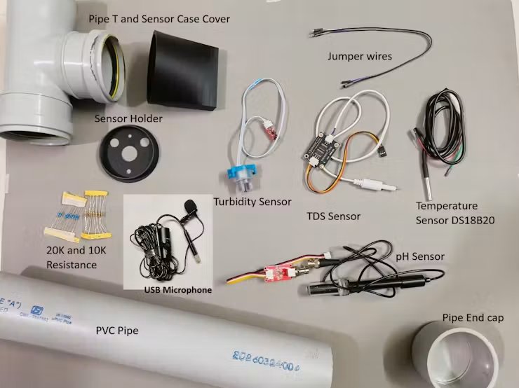
Step 1: Components For 1x Pipe Node Unit:
- 1 x Arduino UNO Q 2GB
- 1 x Turbidity Sensor
- 1 x TDS Sensor
- 1 x Water PH sensor
- 1 x Waterproof temperature sensor (DS18B20)
- 1 x USB Microphone
- 1 x USB-C HUB
- 1 x USB-C cable
- 3 x 20K ohm resistance 0.25 W
- 3 x 10K ohm resistance 0.25 W
- 1 x Communication: LoRa Ra-01 Module (SX1278)
- 1 x Li-Po Battery
- 1 x Li-Po battery charging / V reg module
- 1 x 70x70mm Solar Panel
- 1 x 75mm dia PVC pipe
- 3 x 75mm Pipe End-Cap
- 1 x 75mm Pipe T
Step 2: Pipe Node PCB Making
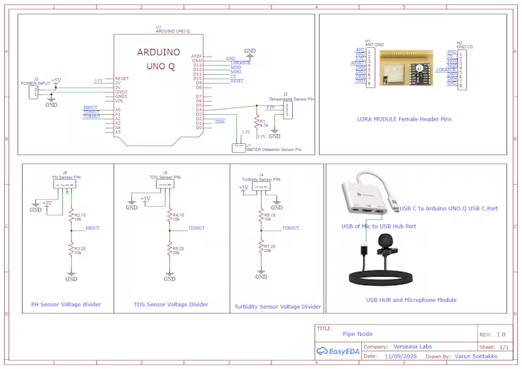
Core Controller (Arduino UNO Q): Serves as the central edge processor, handling multi-sensor data acquisition, TinyML acoustic inference, and wireless communication.
Precision Signal Level-Shifting (10kΩ & 20kΩ Voltage Dividers):
- The Challenge: Water quality sensors (pH, TDS, Turbidity) operate at 5V, but the Arduino UNO Q’s ADC inputs can only safely handle 0–3.3V. Connecting 5V directly risks permanently damaging the microcontroller.
- The Solution: A passive voltage divider with a 10kΩ and 20kΩ resistor network scales the 0–5V sensor output down to a safe 0–3.33V (5V×2010+20=3.33V5V×10+2020=3.33V).

- Data Integrity: These specific resistance values provide the ideal balance—they draw negligible current from the sensors while staying low enough (6.67kΩ source impedance) for the ADC to sample quickly and accurately without signal distortion.
- Firmware Scaling: In code, the original sensor voltage is simply restored by multiplying the reading by 1.5×.
Water Quality Monitoring:
- pH Sensor (A0): Detects chemical contamination and pipe corrosion.
- TDS Sensor (A1): Measures dissolved minerals, salinity, and industrial runoff.
- Turbidity Sensor (A2): Measures water clarity to detect silt, sediment, or pipe cracks.
Digital & Environmental Sensing:
- Temperature Sensor (DS18B20 on D4): Uses a 4.7kΩ pull-up resistor to provide thermal readings for accurate pH/TDS calibration.
- Water Detection Sensor (D3): Identifies surface moisture, flooding, or outer pipe leaks.
Acoustic Edge AI Leak Detection:
- Connects a high-sensitivity USB microphone via a USB hub to the Arduino UNO Q’s USB-C port to listen for underground acoustic pipe hiss and leak vibrations using Edge Impulse TinyML.
Long-Range Telemetry (Ra-01 LoRa Module):
- Communicates via SPI (D9–D13, D2) to transmit telemetry and leak alerts over several kilometers without relying on cellular networks or internet access.
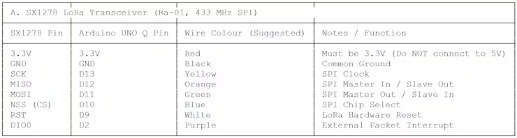
Hardware Pin Configuration Matrix
To maintain clean signal routing and prevent cross-talk on the PCB layout, components were grouped by their communication architecture (SPI, Analog, and 1-Wire) and mapped to the microcontroller as follows:


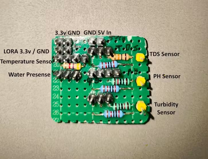
Custom Sensor Interface & Power Distribution Board
- A compact, custom-built proto-board (daughterboard) designed to eliminate messy breadboard wiring.
- Serves as the central hardware bridge between the Arduino UNO Q, external water quality probes, and the Ra-01 LoRa module, integrating signal conditioning and power distribution into one clean, rugged unit.
How It Was Fabricated & Designed:
Precision Voltage Divider Conditioning (Front Side):
- Houses three pairs of through-hole 10kΩ and 20kΩ precision resistors, forming dedicated voltage dividers that step down the 0–5V analogue outputs of the TDS, pH, and Turbidity sensors to a safe 0–3.33V level for the Arduino UNO Q’s ADC.
- Integrates an onboard 4.7kΩ pull-up resistor dedicated to the DS18B20 temperature sensor’s 1-Wire data communication
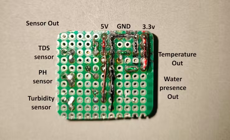
Clean Power Distribution Rails (Back Side):
- Hand-routed, colour-coded power buses soldered on the back side provide isolated, low-impedance rails for +5V (Red), GND (Black), and +3.3V (Red).
- This shared ground and stable rail design prevents ground-loop noise and ensures rock-solid analog readings across all sensors.
Dedicated Sensor & Module Breakouts:
- Features dedicated pin headers labelled for quick connection of the TDS Sensor, pH Sensor, Turbidity Sensor, Temperature Sensor, and Water Presence Sensor.
- Includes dedicated 3.3V and GND power header taps to reliably power the low-voltage Ra-01 LoRa transceiver.
- Provides clearly laid-out tap points (
Sensor Out) for routing the scaled analog and digital signals directly to the controller Interconnection to the Pipe Node (Arduino UNO Q):
Interconnection to the Pipe Node (Arduino UNO Q):
Modular Jumper Wire Harnessing: In accordance with the system schematic, high-grade jumper wires are used to link this interface board to:
- The Arduino UNO Q header pins (routing scaled analog signals to
A0–A2, digital 1-Wire/interrupts toD3–D4, and SPI bus pins). - The external water quality probes and temperature sensor.
- The Ra-01 LoRa module for long-range data transmission.
- The incoming 5V system power supply.
Field Maintenance & Prototyping Advantage: This hybrid approach combines the electrical stability of soldered voltage dividers and power rails with the modular convenience of jumper-wire routing, making it easy to test, calibrate, or swap sensors in the field without desoldering.
Step 3: Pipe Node CAD Design and 3D Printing
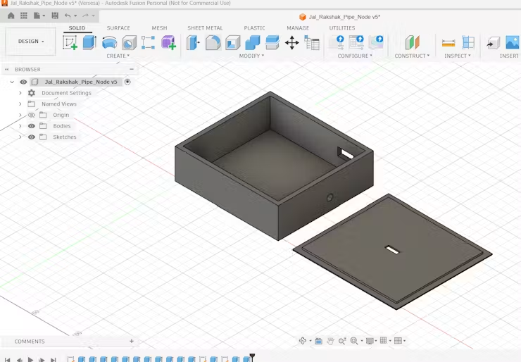
Operating in underground municipal environments means our electronics face a dual threat: mechanical impact and moisture ingress. To safeguard the system, I designed a split-enclosure architecture using Autodesk Fusion 360. Instead of forcing everything into a single bulky box, the system is separated into two specialised units: a centralised processing hub and a localised, waterproof sensor pod.
1. Pipe Node Custom 3D Enclosure Design
All-in-One Compact Housing:
- Designed in Autodesk Fusion 360 to house all Pipe Node electronics securely in a rugged, unified form factor.
- Internal cavity neatly accommodates the Arduino UNO Q, the Ra-01 LoRa module, the custom sensor interface PCB, and an onboard rechargeable battery.
Top Lid with Solar Harvesting Integration:
- Dedicated Solar Panel Mount: The top cover features a recessed flat surface specifically sized to mount the solar panel securely on top.
- Top Cable Passthrough Slot: Includes a center slot in the lid allowing the solar panel’s charging wires to route directly inside to the battery management circuit.
Optimised RF & Cable Routing Openings:
- LoRa Antenna Port: A precision circular cutout on the front face allows the external LoRa antenna to extend outside the enclosure, ensuring unobstructed long-range RF transmission.
- Side Cable & Jumper Wire Passthrough: Features dedicated side rectangular cutouts for easy routing of external jumper wires, water quality sensor cables (pH, TDS, Turbidity, DS18B20), and the USB microphone line without pinching wires.
Field-Ready & Self-Sustained Deployment:
- By combining the internal battery with the roof-mounted solar panel, the enclosure enables true energy-autonomous, continuous field monitoring on remote municipal pipelines without requiring external grid power.
2. Enclosure Architecture 2: The T-Junction Sensor Pod
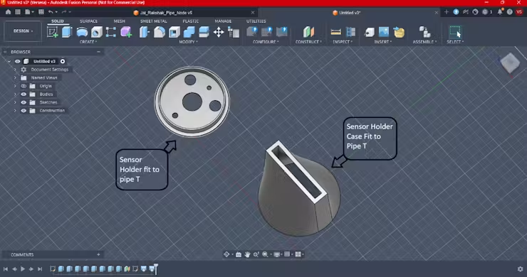
Because water quality sensors must interact directly with the fluid stream, protecting their exposed wiring and delicate breakout circuitry requires an entirely different engineering approach.
- T-Side Pipe Integration: This modular enclosure is engineered to clamp directly onto the “T-side” (T-junction flange) of standard municipal distribution lines, ensuring zero leaks and a flush structural mount.
- Hermetic Circuit Protection: The assembly utilizes a dual-piece system consisting of an internal sensor alignment holder and a heavy-duty, gasket-sealed case cover. This ensures that while the physical probes sit inside the water stream, their delicate terminal boards remain completely dry.
5-in-1 Sensor Array Placement: The holder features internal alignment channels engineered to simultaneously cradle five distinct probes:
- Temperature probe (1-Wire)
- pH electrode
- TDS copper pins
- Turbidity light-scattering probe
- Water Presence Sensor
3. Fabrication & Slicing Profile
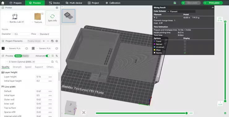
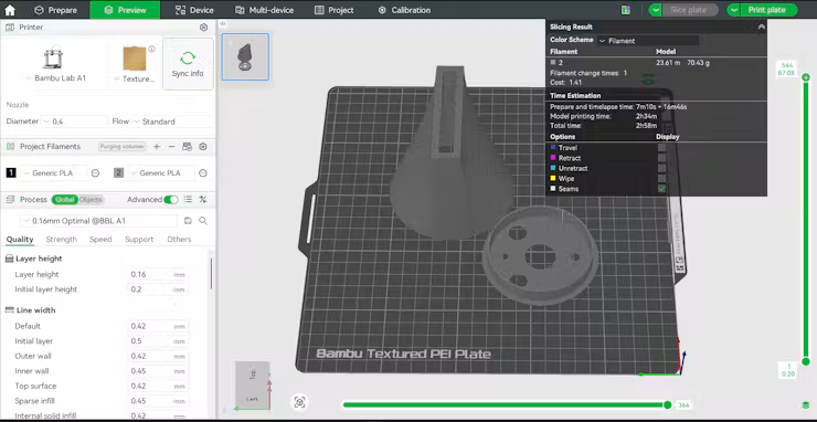
To turn these complex geometric models into rugged, field-deployable plastic parts, the slicing and manufacturing workflow was tightly controlled to maximise water resistance and interlayer bond strength.
- Production Hardware: Fabricated using a Bambu Lab A1 3D printer. The machine’s large build volume allowed multiple enclosure panels to be printed simultaneously, maintaining perfect dimensional tolerance across matching parts.
- Slicing Engine: All models were processed through Bambu Studio to configure optimised path planning, ensuring clean vertical walls around the critical sensor o-ring grooves.
- Material Selection (PLA+): Standard PLA was rejected due to its brittleness under mechanical stress. I utilized premium PLA+, which offers significantly higher impact resistance and superior interlayer adhesion—a necessity for enduring subterranean pressure variants.
Print Settings Profile:
- Nozzle Diameter: 0.4mm (Balances precise internal snapping clips with robust outer walls)
- Layer Height: 0.16mm (High-quality fine resolution to minimise stair-stepping on threaded sections and ensure watertight seals)
- Infill Density: 25% Gyroid (Provides uniform multi-directional structural strength against ground compression)
- Wall Loops: 3 Layers (Thick outer shell to prevent micro-porosity water leaking through layers)
Files for Pipe Node 3D CAD file are available in the GitHub repository: link
Step 4: Pipe Node Solar Wiring and Power setup
To ensure total energy independence from the main power grid, the Pipe Node utilizes a self-sustaining solar harvesting subsystem. The core of this power architecture is an All-in-One 5V Step-Up Charge Controller Module. This module acts as the energy traffic controller, it safely manages variable solar voltage to charge a high-capacity Lithium-Polymer (LiPo) battery while simultaneously boosting the battery’s nominal 3.7V output to a rock-solid 5V rail required by the water quality sensors.
The electrical wiring and assembly sequence were performed in the following precise order:
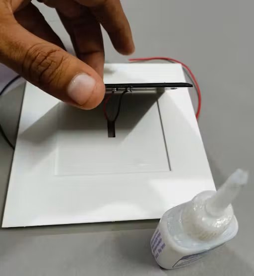
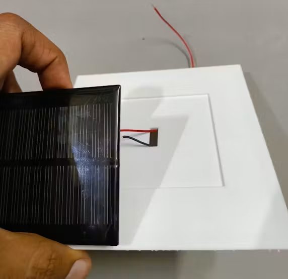
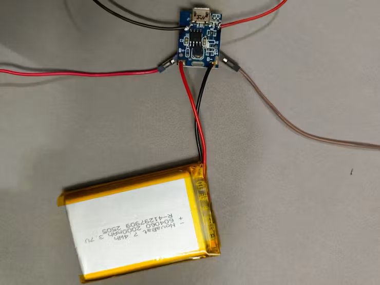
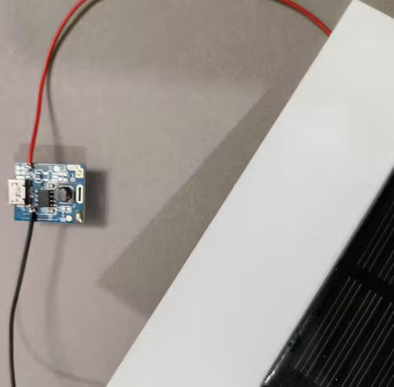
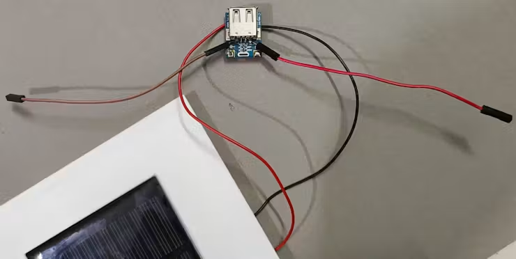
- Step 1: Solar Panel Input Integration: The positive and negative leads from the outdoor-rated solar panel were routed into the housing and soldered directly to the Solar Input pads (VIN+ / VIN-) on the charge controller module. This establishes the primary power harvesting pathway.
- Step 2: 5V Regulated Output Routing: To supply power to the sensor array and the main circuit, heavy-gauge jumper wires were soldered to the 5V Boost Output pads (VOUT+ / GND) of the module. These wires run directly to the power distribution rails on our main Pipe Node PCB.
- Step 3: LiPo Energy Storage Connection: The final connection involved soldering the positive (Red) and negative (Black) leads of the 3.7V LiPo battery to the dedicated Battery Terminals (B+ / B-) on the controller. Keeping this step for last prevents the boost circuitry from running in an unstable, unbuffered state while handling loose wires.
Step 5: Pipe Node Housing, Wiring & Power Assembly
This section outlines the step-by-step mechanical assembly, modular jumper wiring, and isolated dual-power setup for the Jal Rakshak Pipe Node.
Step1: T-Junction Sensor Pod Integration
This phase couples the water quality probes with the structural plumbing elements using a rugged, multi-sensor alignment array.
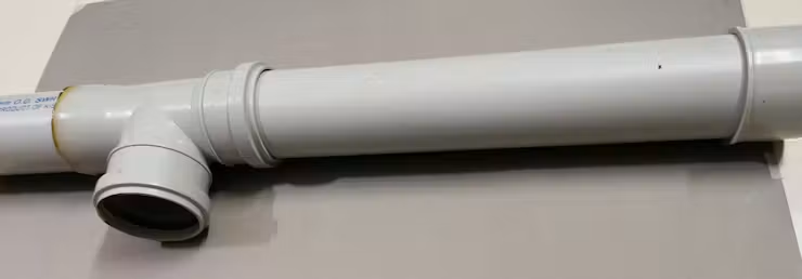
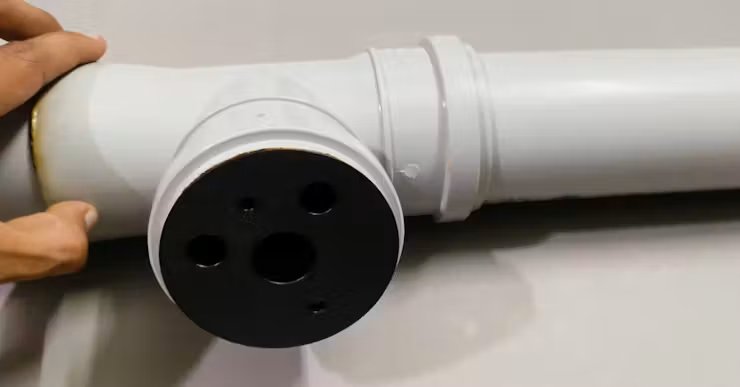
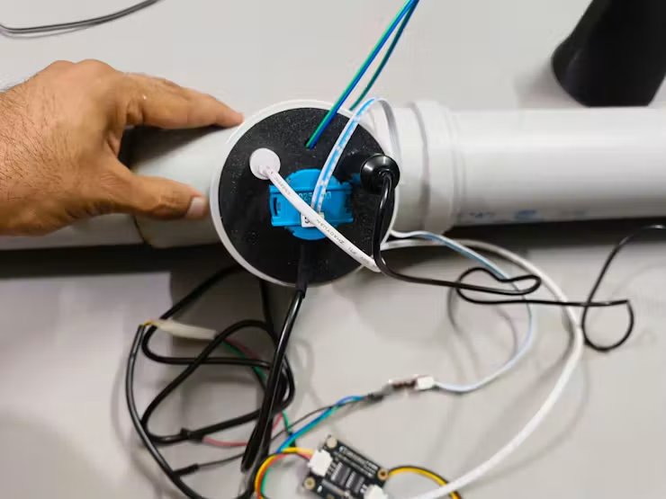
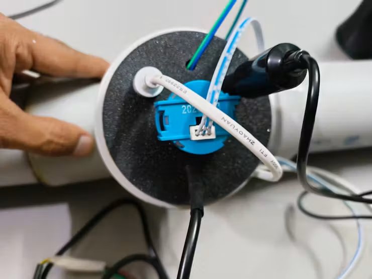
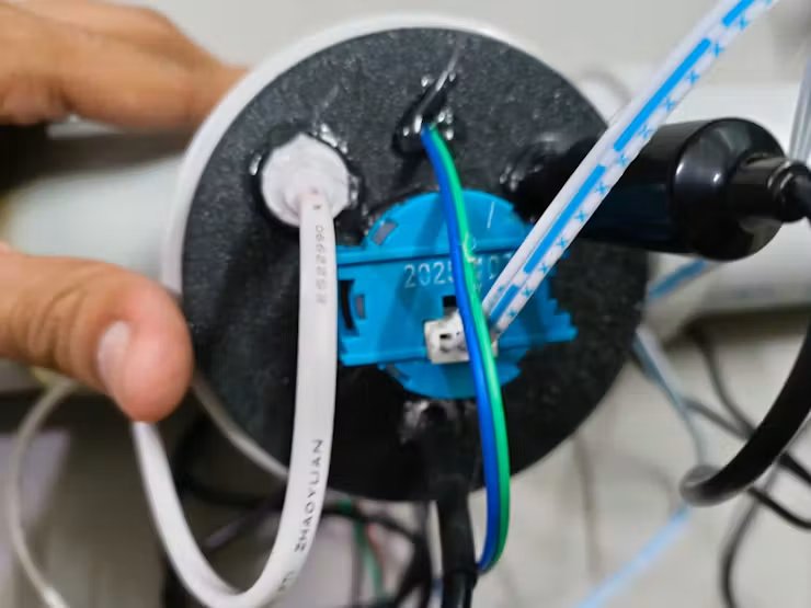
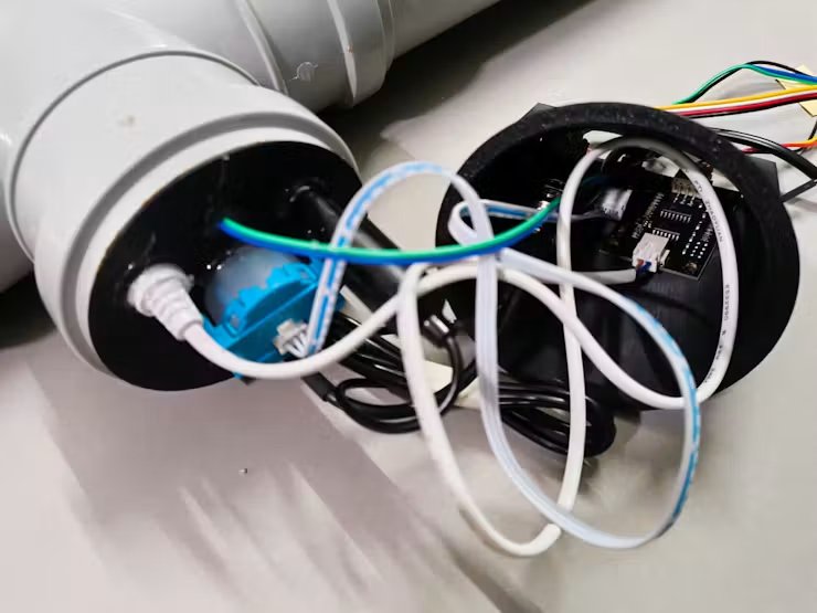
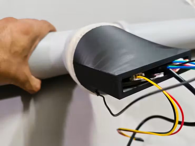
T-Pipe Assembly & Probe Mounting
- Fit your structural PVC pipes securely into both straight ends of the plumbing T-junction.
- Apply a generous layer of high-strength adhesive (like Fevi-bond or PVC solvent cement) to attach the custom 3D-printed sensor holder to the third (orthogonal) opening of the T-junction.
- Insert the five core probes (Temperature, pH, TDS, Turbidity, and Water Presence) into their form-fitting alignment channels.
- Pack the external mounting side heavily with M-Seal wet-set epoxy putty to create a permanent, pressure-resistant seal around the probe bodies.
Converter Board Layout: Connect the raw analogue leads from the pH, TDS, and Turbidity probes to their respective signal conditioner/converter breakout boards.
- Line the interior base of the separate 3D-printed sensor case with high-bond double-sided tape and press the converter boards down into an organised grid layout.
Harness Extraction & Pod Sealing: Carefully group all wiring harnesses, ensuring every single lead is explicitly labeled or color-identified by sensor type before it is covered.
- Route the entire bundled wiring harness cleanly out of the sensor housing. Mount the sensor case directly over the pipe T-junction mechanism, shielding the fragile electronics, and seal all exterior seams completely with M-Seal wet-set putty.
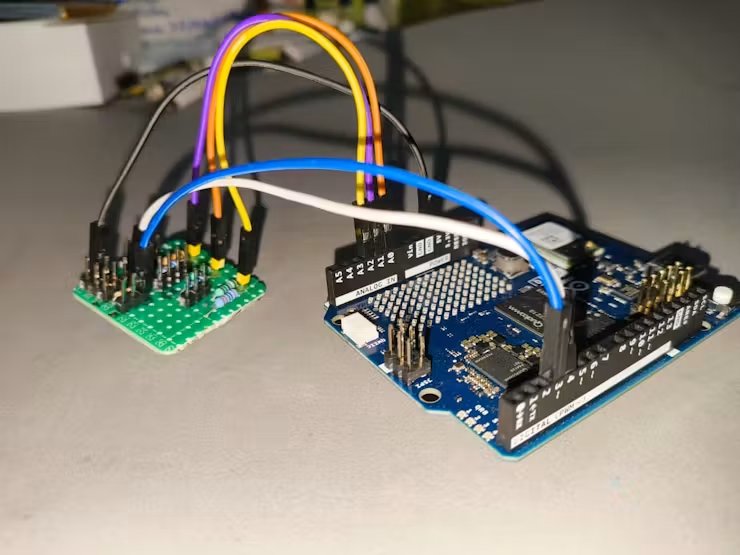
Step 2: Connecting the Sensor Interface PCB to Arduino UNO Q
Analogue Signal Routing: Use female-to-male jumper wires to connect the scaled sensor outputs from the Sensor Connect PCB directly to the Arduino UNO Q analog pins:
PHOUT[Orange]→→ A0TDSOUT[Purple]→→ A1TUROUT(Turbidity) [Yellow]→→ A2
Digital Sensor Routing: Connect the pre-conditioned digital lines:
- Temperature Sensor Data Line (with onboard 4.7kΩ pull-up) [white]→→ D4
- Water Presence Detection Line [Blue] →→ D3
Reference Ground: Connect a jumper wire between the GND rail of the Sensor Connect PCB and the GND pin of the Arduino UNO Q to ensure a shared common reference.[Black]
Step 3: Ra-01 LoRa Module Interfacing
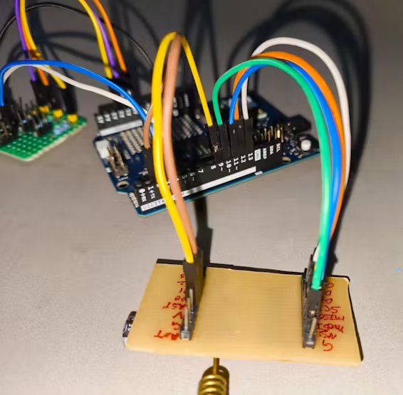
SPI Bus Wiring: Connect the Ra-01 LoRa module to the Arduino UNO Q using short jumper wires to maintain high SPI signal integrity:
SCK→→ D13MISO→→ D12MOSI→→ D11NSS / CS→→ D10RESET→→ D9DIO0(Packet Rx Interrupt) →→ D2
Power Connection: Connect the LoRa module’s 3.3V and GND pins directly to the dedicated 3.3V power header tap on the Sensor Connect PCB.
Step 4: Implementing the Dual-Power Subsystem
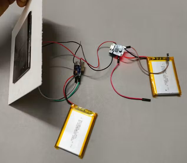
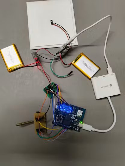
To isolate sensitive analogue sensor measurements from microcontroller switching noise and ensure stable operation, a dual-rail battery architecture is implemented:
Rail 1 (Processing Core & Low-Voltage Digital Rail):
- LiPo Battery #1 feeds a dedicated 5V boost regulator, which powers the Arduino UNO Q via its USB-C port.
- The Arduino UNO Q’s onboard regulator generates a clean 3.3V rail, routed via jumper wire to the 3.3V bus on the Sensor Connect PCB.
- This 3.3V rail safely powers the Ra-01 LoRa module, DS18B20 Temperature sensor, and Water Presence sensor.0
Rail 2 (Isolated 5V Analogue Sensor Rail):
- A separate LiPo Battery #2 and dedicated 5V boost regulator supply power directly to the 5V In terminal of the Sensor Connect PCB.
- This rail exclusively powers the active operational amplifiers and photodiodes of the pH, TDS, and Turbidity sensor breakout boards.
- Common Ground: Both power rails share a tied system ground across the PCB to maintain accurate ADC measurements without ground loops.
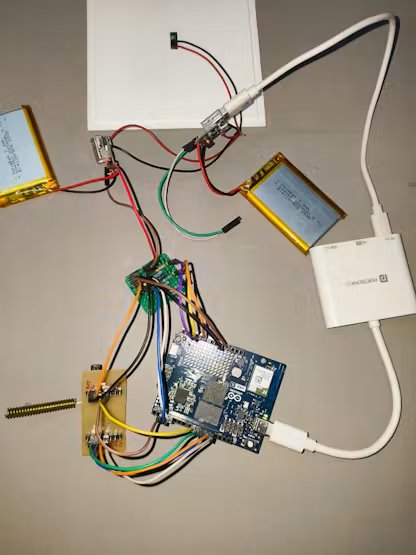
Step 5: Internal Enclosure Mounting & Cable Passthrough
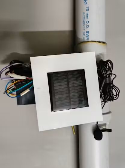
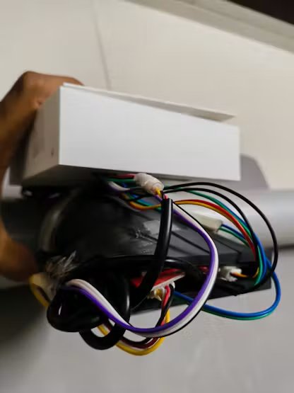
- Internal Component Seating: Place the Arduino UNO Q, Ra-01 LoRa module, Sensor Connect PCB, and dual battery packs into the lower compartment of the 3D-printed enclosure using high-bond double-sided mounting tape.
- LoRa Antenna Routing: Route the external LoRa antenna through the front circular cutout so it protrudes outward for maximum RF transmission range.
- Sensor & Mic Cabling: Pass the external water probe wires and the acoustic USB lapel microphone cable cleanly through the side rectangular cutouts without wire pinch.
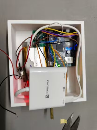
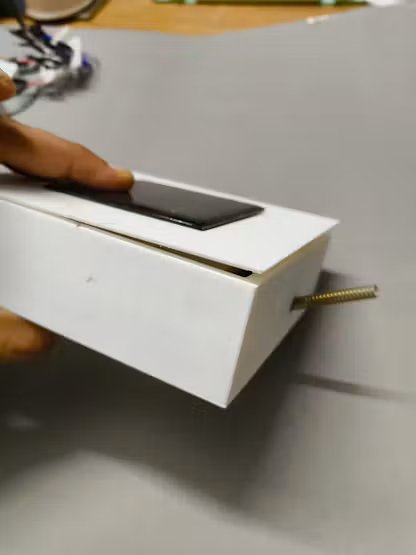
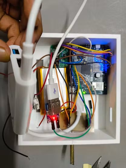
Step 6: Enclosure Lid, Solar Integration & Final Sealing
- Solar Panel Mounting: Mount the compact solar panel onto the recessed top face of the enclosure lid.
- Solar Wire Routing: Pass the solar panel’s charging leads through the center lid hole into the enclosure and connect them to the battery charging circuit.
- Sensors Connect: Connect the TDS, PH, Turbidity, Temperature and water presense sensor wires to sensor conect PCB.
- Lid Seating & Weatherproofing: Secure the top cover onto the main chassis, sealing wire entry ports with silicone or M-Seal putty to prevent moisture ingress during subterranean pipeline deployments.
Part B: Pipe Node Code & Edge AI Deployment
Step 1: Pipe Node Acoustic Edge AI Setup
Underground pipe fractures emit distinct high-frequency acoustic hiss and vibration patterns under pressure. To capture and classify these acoustic signatures directly at the edge, a TinyML acoustic classification model was developed using Edge Impulse and deployed on the Arduino UNO Q.
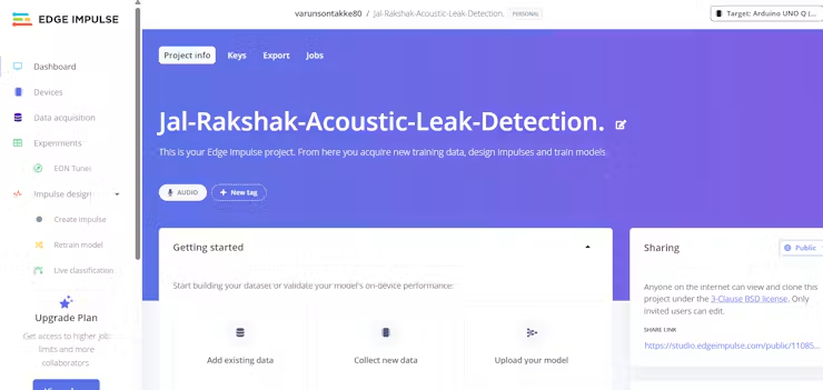
Edge Impulse Project Creation:
- Created a dedicated project on the Edge Impulse Studio named
Jal-Rakshak-Acoustic-Leak-Detection. - Set the target device to Linux (Qualcomm Dragonwing MPU on Arduino UNO Q) and selected the sensing modality as Audio / Acoustic Sensing.
Hardware Rig & Microphone Coupling:
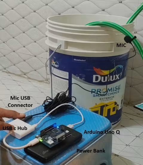
- Connected a multi-port USB Hub to the high-speed USB-C port of the Arduino UNO Q.
- Plugged a high-sensitivity USB lapel/boundary microphone into the hub.
- Acoustically coupled the microphone directly to the exterior wall of the PVC test pipe using a secure mechanical mount, dampening ambient airborne sound while maximizing pipe-wall vibration transfer.
Data Ingestion via Terminal:
- Opened the serial/SSH terminal on the Arduino UNO Q Linux shell.
- If you are doing this First time then do check this documentation to set up edge impuse data collection in Arduino Uno Q.
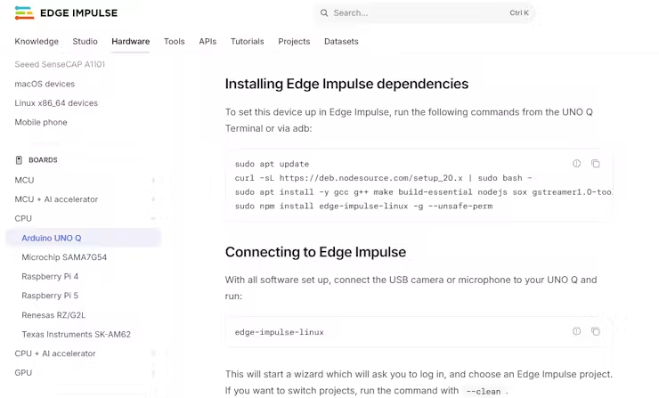
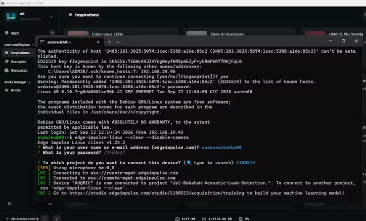
- Executed the Edge Impulse data collection to pair the board directly with the studio:
bash
edge-impulse-linux --clean --disable-camera- Verified that the USB microphone was recognized as the active audio capture input at a 16 kHz sampling frequency
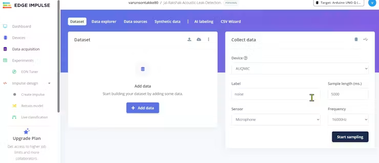
Dataset Collection & Sound Profiling:
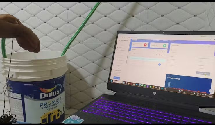
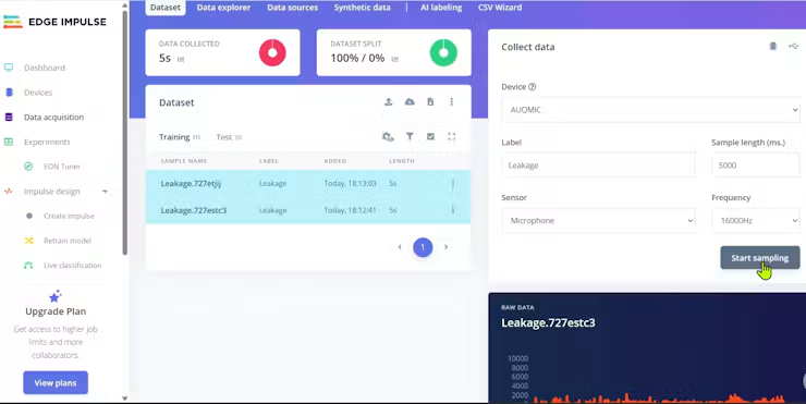
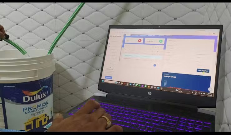
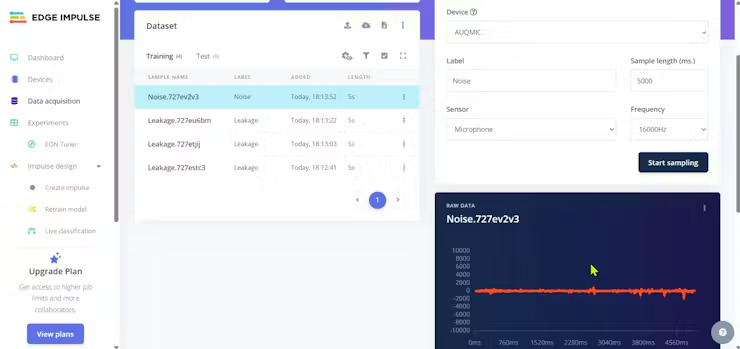
Link for video tutorial how acoustic Edge AI data is collected.
- Leak Class (L
eak): Pressurized the pipeline and induced realistic pinhole leaks and crack releases, capturing continuous acoustic hiss, turbulent flow sounds, and structural pipe resonances. - Ambient Class (N
oise): Recorded realistic non-leak noise profiles, including background vehicle traffic, street rumbling, pedestrian footsteps, pump motor hums, and pipeline resting silence to prevent false alarms. - Balanced the dataset with several minutes of audio split automatically into 5000 ms sliding windows.
Impulse Design (Feature Extraction & Neural Network):
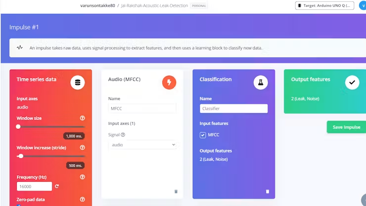
- Time Series Audio Block: Configured a window size of 1000 ms with a window increase of 500 ms at a 16 kHz sampling rate.
- Processing Block (MFE / MFCC): Selected Mel-Frequency Energy (MFE) feature extraction, which generates spectrograms specifically tuned to capture acoustic energy peaks in the 2 kHz to 8 kHz band where pressurised pipe hissing dominates.
- Learning Block (Classification): Configured a 1D/2D Convolutional Neural Network (CNN) classifier capable of distinguishing leak spectrogram patterns with low latency.
Model Training & Validation:
- Trained the neural network over 40 epochs with a learning rate of 0.005 and data augmentation enabled.
- Achieved >95% accuracy on validation samples with clear separation between background street rumbling and structural leak hisses.
- Downloaded and packaged the model artifact for the Arduino App Lab deployment pipeline.
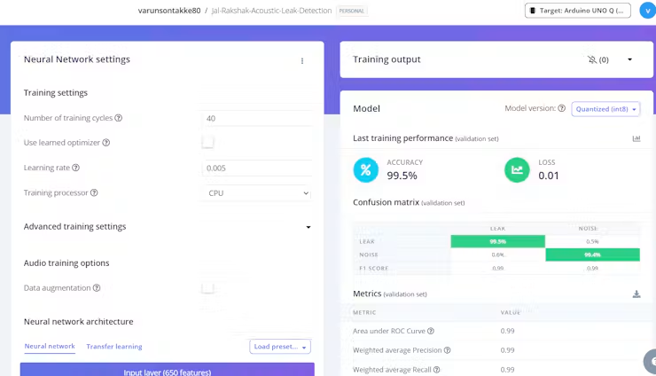
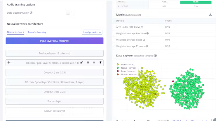
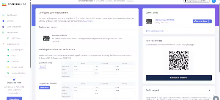
Link for Edge AI project Jal-Rakshak-Acoustic-Leak-Detection
Step 2: Pre-Requisite App Lab Setup for Pipe Nodes
The Arduino App Lab environment integrates Python-driven containerized microservices (“bricks”) on the Linux MPU with real-time firmware running on the STM32 MCU.
Account Authentication:
- Launched Arduino App Lab and authenticated with both the official Arduino Account and linked Edge Impulse developer credentials.
- Ensured the Arduino UNO Q was recognised and active over the local connection.
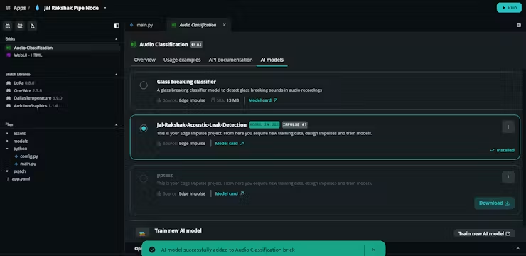
Deploying the Acoustic Edge AI Brick:
- Configured the node’s
app.yamlmanifest to declare the official audio classification and local diagnostic WebUI bricks:
yaml
name: Jal Rakshak Pipe Node
description: "Underground water pipe monitoring node - Acoustic AI leak detection via USB
microphone, multi-parameter water quality sensors, and LoRa uplink to Master Node"
ports: []
bricks:
- arduino:audio_classification:
   model: ei-model-1022382-1
- arduino:web_ui: {}
icon: 💧- Linked the downloaded Edge Impulse acoustic model into the
arduino:audio_classificationbrick, enabling the Linux runtime to feed live USB microphone audio into the AI model in real time.
Setting Deployment GPS Coordinates in Code:
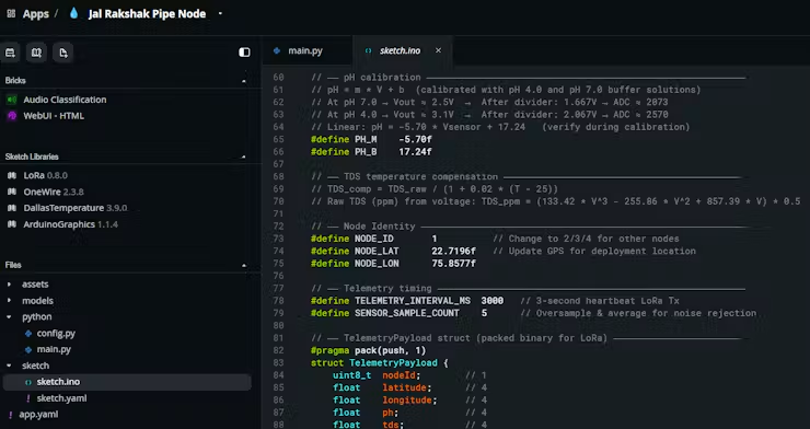
- To ensure precision GIS mapping on the Master Node dashboard, static deployment GPS coordinates and Node ID are set inside the firmware and Python configurations:
- In
sketch/sketch.ino:
cpp
// ── Node Identity & GIS Coordinates ───────────────────────────
#define NODE_ID       1          // Unique Pipe Node ID (1, 2, 3, etc.)
#define NODE_LAT      22.7196f   // Physical latitude of pipe segment
#define NODE_LON 75.8577f // Physical longitude of pipe segment- In
python/main.py:
python
# Default location state for local diagnostic WebUI
sensor_state = {
   "nodeId": 1,
   "latitude": 22.7196,
   "longitude": 75.8577,
   ...
}
Step 3: Upload Code and Code Logic for Pipe Nodes
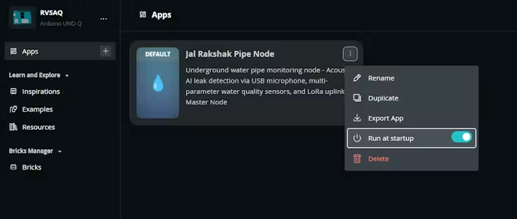
Configuring Startup Execution in Arduino App Lab:
- Enabled auto-start on boot in Arduino App Lab for the
JalRakshakPipeNodeapplication. - This guarantees that whenever the solar battery system boots or recovers from low voltage, the Linux MPU initiates the Python AI service, starts sensor acquisition, and begins LoRa telemetry without any manual intervention
Pipe Node Code Architecture Flowchart:
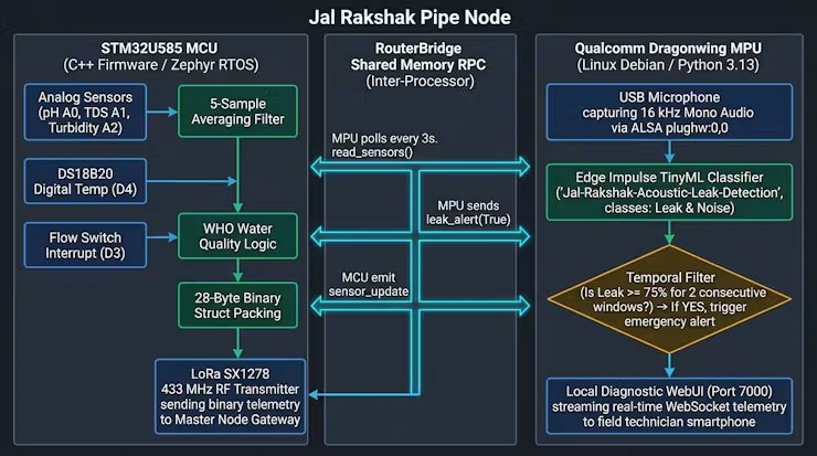
1. Dual-Processor Inter-IPC via RouterBridge
- Dual-Brain Task Separation: The Arduino UNO Q leverages an asymmetrical multiprocessing (AMP) architecture. The quad-core Qualcomm Dragonwing QRB2210 Linux MPU executes continuous Edge AI neural inference and hosts the local diagnostic WebUI, while the STM32U585 MCU (Zephyr RTOS) handles microsecond hardware timing, 12-bit analog oversampling, and SPI timing for the LoRa radio.
- Shared-Memory MessagePack RPC: Communication between processors occurs via
Arduino_RouterBridgeover internal shared memory without network overhead. The MPU pulls sensor telemetry every 3 seconds, and notifies the MCU immediately upon acoustic leak confirmation.
python
# python/main.py — MPU Polling STM32 MCU via Bridge RPC
def poll_sensors():
   """Poll MCU for latest multi-parameter sensor readings every 3 seconds."""
   raw = Bridge.call("read_sensors", "")
   if raw and "," in str(raw):
       fields = str(raw).strip().split(",")
       # Format: nodeId,lat,lon,pH,TDS,Turb,Temp,waterPresence,leakAlert,emergencyFlag
       sensor_state.update({
           "ph":          round(float(fields[3]), 2),
           "tds":         round(float(fields[4]), 1),
           "turbidity":   round(float(fields[5]), 1),
           "temperature": round(float(fields[6]), 1),
           "leakAlert":   fields[8] == "1",
           "emergency":   fields[9] == "1"
       })
       _broadcast_ui()
cpp
// sketch/sketch.ino — STM32 MCU Exposing Bridge RPC Endpoints
void setup() {
   Bridge.begin();
   Bridge.provide("read_sensors",     read_sensors);
   Bridge.provide_safe("trigger_lora_tx", trigger_lora_tx);
   Bridge.provide_safe("leak_alert",  on_leak_alert);
}
void on_leak_alert(bool detected) {
   leakAlert = detected;
   if (detected) {
       forceTx = true;  // Bypass 3-second timer for instant emergency LoRa transmission
       Serial.println("[ACOUSTIC AI] Leak confirmed by MPU! Broadcasting emergency LoRa
alert.");
   }
}
2. Continuous Edge AI Acoustic Classification & Temporal Filter (main.py)
- Direct ALSA Hardware Capture: Audio is continuously captured at 16, 000 Hz (16-bit Mono PCM) from the USB hydrophone/microphone using direct ALSA binding (
plughw:0,0), bypassing container udev restrictions. - Continuous Runner Hook (
infer_from_features): Rather than relying on rigid threshold-only triggers, the Python layer interceptssc.infer_from_featuresdirectly from the Edge Impulse runner container (ei-audio-classifier-runner:1337). This delivers real-time probability distributions betweenLeak(cavitation hiss) andNoise(ambient laminar flow) every ~400 ms. - Temporal Consistency Filter: To prevent transient ambient disturbances (such as road traffic, hammer knocks, or footsteps) from triggering false alarms, the system requires P(Leak)≥0.75P across two consecutive sliding windows before confirming a leak and escalating to the physical MCU.
python
# python/main.py — Hooking Edge Impulse Runner for Continuous Streaming
orig_infer = sc.infer_from_features
def wrapped_infer(features):
   """Intercept raw Edge Impulse inferences on every 400ms sliding window."""
   res = orig_infer(features)
   if res and "result" in res and "classification" in res["result"]:
       on_audio_classified(res["result"]["classification"])
   return res
sc.infer_from_features = wrapped_infer
# python/main.py — Temporal Consistency Filter & Alert Escalation
def on_audio_classified(class_map: dict):
   global acoustic_state
   best_label = max(class_map, key=class_map.get)
   best_conf  = float(class_map[best_label])
   # Check for Leak classification
   if "leak" in best_label.lower() and best_conf >= LEAK_CONFIDENCE_THRESHOLD:
       acoustic_state["consecutive_leak_count"] += 1
   else:
       acoustic_state["consecutive_leak_count"] = 0
   # Require 2 consecutive high-confidence windows (1.0s sustained acoustic anomaly)
   previously_confirmed = acoustic_state["leak_confirmed"]
   acoustic_state["leak_confirmed"] = (
       acoustic_state["consecutive_leak_count"] >= CONSECUTIVE_WINDOWS_REQUIRED
   )
   if acoustic_state["leak_confirmed"] and not previously_confirmed:
       logger.warning(f"🚨 ACOUSTIC LEAK CONFIRMED! P({best_label})={best_conf:.3f}")
       Bridge.notify("leak_alert", True)  # Alert STM32 to force immediate LoRa packet
3. High-Precision Sensor Conversion, Oversampling & Thermal Compensation (sketch.ino)
- 12-Bit ADC Oversampling & Restoration: Analog water quality sensors (pH on
A0, TDS onA1, Turbidity onA2) output 0–5V signals, which pass through 10kΩ:20kΩ precision voltage dividers to protect the 3.3V STM32 pins. The MCU samples the 12-bit ADC (4095.0f) over 5 iterations and multiplies by 1.5×1.5× (30kΩ/20kΩ) to mathematically restore the true 0–5V sensor potential. - Dynamic Temperature Compensation: Water electrical conductivity varies by ~2% per °C. The firmware acquires temperature in real time from the DS18B20 1-Wire sensor (
D4) and applies thermal compensation to the TDS polynomial regression to ensure accurate readings regardless of seasonal weather shifts. - Instant Flow Detection: A digital flow switch on
D3operates via hardware interrupt (attachInterrupt), instantly detecting pipeline dry-out or negative-pressure suction conditions.
cpp
// sketch/sketch.ino — ADC Oversampling & True Voltage Restoration
float readVoltageSensor(int pin) {
   long sum = 0;
   for (int i = 0; i < SENSOR_SAMPLE_COUNT; i++) {
       sum += analogRead(pin);
       delayMicroseconds(200);
   }
   float vadc = ((float)sum / SENSOR_SAMPLE_COUNT / 4095.0f) * 3.3f; // 12-bit resolution
   return vadc * 1.50f; // Voltage divider restoration (10k top / 20k bottom)
}
// sketch/sketch.ino — DS18B20 Temperature-Compensated TDS Calculation
float readTDS(float tempC) {
   float v = readVoltageSensor(PIN_TDS);
   float rawTDS = (133.42f * v * v * v - 255.86f * v * v + 857.39f * v) * 0.5f;
   // Standard 2%/°C temperature compensation relative to 25°C baseline
   float compensationCoefficient = 1.0f + 0.02f * (tempC - 25.0f);
   float compensatedTDS = rawTDS / compensationCoefficient;
   return constrain(compensatedTDS, 0.0f, 1500.0f);
}
4. Compact 28-Byte Binary LoRa Telemetry Serialization (sketch.ino)
- Bandwidth Optimization: In underground subterranean environments, high airtime drains node power and causes packet collision. Rather than transmitting inefficient JSON or CSV strings, the Pipe Node serializes all telemetry into a compact, 28-byte packed binary struct (
#pragma pack(push, 1)). - Deterministic Packing: Transmits physical quality parameters, GPS coordinates, flow state, acoustic leak status, and emergency flags within a single sub-second RF burst over 433 MHz LoRa (SF7, BW 125 kHz).
cpp
// sketch/sketch.ino — 28-Byte Packed Binary Telemetry Structure
#pragma pack(push, 1)
struct TelemetryPayload {
   uint8_t  nodeId;        // 1 byte  (Node ID 1-4)
   float    latitude;      // 4 bytes (IEEE 754 float)
   float    longitude;     // 4 bytes (IEEE 754 float)
   float    ph;            // 4 bytes (0.00 - 14.00 pH)
   float    tds;           // 4 bytes (ppm)
   float    turbidity;     // 4 bytes (NTU)
   float    temperature;   // 4 bytes (°C)
   bool     waterPresence; // 1 byte  (Flow active)
   bool     leakAlert;     // 1 byte  (Acoustic cavitation)
   bool     emergencyFlag; // 1 byte  (Contamination / Critical breach)
};                          // Total = 28 bytes
#pragma pack(pop)
// sketch/sketch.ino — Binary Transmission over Ra-01 LoRa
void transmitTelemetry(float ph, float tds, float turb, float temp, bool flow, bool leak, bool
emg) {
   TelemetryPayload pkt;
   pkt.nodeId        = NODE_ID;
   pkt.latitude      = NODE_LAT;
   pkt.longitude     = NODE_LON;
   pkt.ph            = ph;
   pkt.tds           = tds;
   pkt.turbidity     = turb;
   pkt.temperature   = temp;
   pkt.waterPresence = flow;
   pkt.leakAlert     = leak;
   pkt.emergencyFlag = emg;
   LoRa.beginPacket();
   LoRa.write((uint8_t*)&pkt, sizeof(TelemetryPayload));
   LoRa.endPacket();
}
5. Hybrid Transmission Engine: 3s Periodic Heartbeat & Instant Emergency Interrupt
(sketch.ino)
- Dual-Trigger Transmission Loop: Under routine operational conditions, the node broadcasts telemetry every 3000 ms (
TELEMETRY_INTERVAL_MS) to maintain network liveliness with the Master Gateway. - Zero-Latency Emergency Override: If either the Edge AI acoustic model flags a leak (
leakAlert == true) or physical water quality parameters violate WHO drinking water standards (e.g. pH<6.5 or >8.5, TDS>500ppm, Turbidity>50NTU), the system setsforceTx = true. This immediately bypasses the 3-second delay timer and broadcasts an unscheduled emergency LoRa packet to alert municipal authorities within milliseconds.
cpp
// sketch/sketch.ino — Non-Blocking Dual-Trigger Main Execution Loop
void loop() {
   unsigned long now = millis();
   bool doTx = forceTx || ((now - lastTxMs) >= TELEMETRY_INTERVAL_MS);
   if (doTx) {
       forceTx = false;
       lastTxMs = now;
       float temperature = readTemperature();
       float ph          = readPH();
       float tds         = readTDS(temperature);
       float turbidity   = readTurbidity();
       bool  waterPres   = waterPresence;
       bool  emergency   = checkEmergency(ph, tds, turbidity) || leakAlert;
       // Broadcast binary telemetry over LoRa
       transmitTelemetry(ph, tds, turbidity, temperature, waterPres, leakAlert, emergency);
       // Notify MPU so local diagnostic WebUI reflects the latest broadcast
       notifyMpuSensorUpdate(ph, tds, turbidity, temperature, waterPres, leakAlert, emergency);
   }
   delay(10); // Yield to keep RouterBridge responsive
}
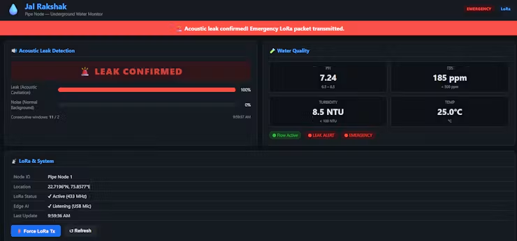
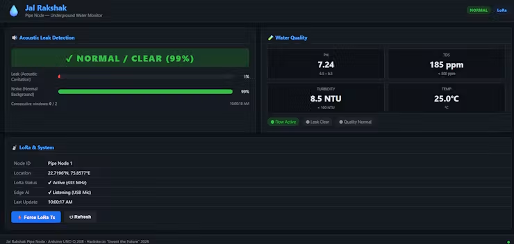
6. Local Diagnostic WebUI for Field Technicians (assets/app.js)
- Zero-Internet Architecture: Because Pipe Nodes are deployed underground without cellular connectivity, the node does not transmit data to Firebase. Instead, it hosts a lightweight, local diagnostic WebUI on port 7000.
On-Site Smartphone Connectivity: Field maintenance crews connect directly to the Pipe Node’s local Wi-Fi and open http://<pipe-node-ip>:7000 on their mobile browser. The client connects via WebSocket (WebUI brick) and visualizes:
- Live, continuous Edge AI confidence bars for
Noise (Normal Background)andLeak(Acoustic Cavitation). - Physical sensor values (pH, TDS, Turbidity, Temp).
- Real-time LoRa packet confirmation and manual transmission trigger button (⚡
Force LoRa Tx).
javascript
// assets/app.js — Real-Time WebSocket Edge AI Visualization
ui.on_message("audio_update", (raw) => {
   const data = extractData(raw);
   const leakPct = Math.round((data.classifications?.Leak || 0) * 100);
   const noisePct = Math.round((data.classifications?.Noise || 0) * 100);
   // Smoothly animate confidence bars on field technician's screen
   document.getElementById("bar-leak").style.width = leakPct + "%";
   document.getElementById("bar-noise").style.width = noisePct + "%";
   document.getElementById("pct-leak").textContent = leakPct + "%";
   document.getElementById("pct-noise").textContent = noisePct + "%";
   const label = document.getElementById("ai-label");
   if (data.leak_confirmed) {
       label.textContent = "🚨 LEAK CONFIRMED";
       label.className = "ai-label danger";
   } else {
       label.textContent = `✔ NORMAL / CLEAR (${noisePct}%)`;
       label.className = "ai-label safe";
   }
});
Local Diagnostic WebUI
4. Building the Master Gateway
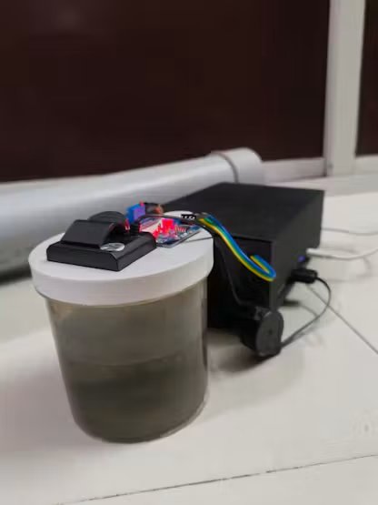
The Master Gateway serves as the centralized brain of the Jal Rakshak system. It is designed to bridge the gap between subterranean edge hardware and municipal decision-makers. Operating above ground, the gateway continuously listens for incoming emergency packets from underground Pipe Nodes over LoRa, coordinates local biochemical validation via an integrated Water Testing Cup, and streams live infrastructure metrics to the cloud via Wi-Fi.
Part A: Hardware Fabrication & Assembly For Master Node
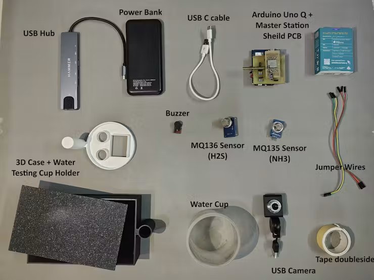
Step 1: Components For 1x Master Gateway Unit:
- 1 x Arduino UNO Q 4GB
- 1 x USB Camera
- 1 x USB C HUB
- 1 x Communication: LoRa Ra-01 Module (SX1278)
- 1 x MQ-135 Ammonia (NH₃) Gas Sensor
- 1 x MQ-136 Hydrogen Sulfide Gas Sensor
- 2 x 20K ohm resistance 0.25 W
- 2 x 10K ohm resistance 0.25 W
- 1 x Buzzer
- 1 x Power Bank 10000mah
- 1 x USB c Cable
- 20 x Jumper Wires
Step 2: Master Node PCB Making
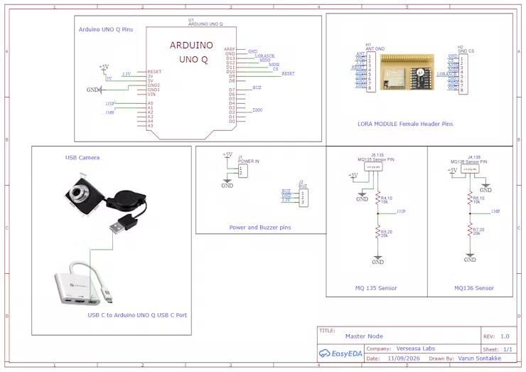
Hardware Architecture: Master Node Schematic & Circuit Design
While the field-deployed Pipe Nodes serve as the frontline underground sensing grid, the Master Node functions as the centralized command hub and intelligence gateway of the entire Jal Rakshak architecture. Built around the Arduino UNO Q, it orchestrates multiple high-throughput tasks simultaneously: aggregating subterranean LoRa telemetry packets, running localized biochemical validation on suspicious water samples via an integrated Water Testing Cup, driving vision-based AI water inspection over USB-C, and sounding an immediate acoustic buzzer alarm during critical contamination events.The Engineering Challenges & Circuit Solutions
None
+--------------------------------------------------+
|                 ARDUINO UNO Q                    |
|                                                  |
[+5V Power] ----->| 5V, GND                                          |
[MQ135 Gas]  ----->| 10k:20k Divider ---> A0 (135P - Ammonia)         |
[MQ136 Gas]  ----->| 10k:20k Divider ---> A1 (136P - H2S Toxic Gas)   |
[Active Buzzer] <--| Direct 3.3V Drive -> D7 (BUZ Alarm Output)       |
[Ra-01 LoRa] <---->| SPI + DIO0      ---> D2, D9–D13 (Telemetry Gateway)
[USB Camera] ----->| USB-C Port      ---> Linux MPU (Vision AI / UV)  |
+--------------------------------------------------+
Engineering Challenges & Circuit Solutions
Logic Level Protection for Sewer Gas Sensors (MQ135 & MQ136):
- The Social Impact Challenge: The catastrophic contamination of municipal drinking water networks is overwhelmingly caused by underground sewage cross-contamination. To specifically detect raw sewage infiltration at the testing cup, the gateway integrates an MQ135 (Ammonia / Organic Pollutants) and an MQ136 (Hydrogen Sulfide H2S) electrochemical gas sensor array.
- The Electrical Mismatch: These industrial gas sensors require a constant 5V heating voltage to activate their internal tin-dioxide (SnO2) chemical sensing elements and produce a proportional 0–5V analog output curve. However, the Arduino UNO Q’s analog inputs operate with a 3.3V ADC ceiling. Exposing the UNO Q pins directly to 5V would destroy the internal microcontroller circuitry.
Passive Precision Voltage Divider Networks:
- Each sensor channel features an independent, low-noise voltage divider using a 10kΩ series resistor (Rtop) and a 20kΩ pull-down resistor (Rbottom) (R4/R5for MQ135 and R6/R7 for MQ136).
- This precisely steps down the 0–5V analog sweep to a safe 0–3.33V scale, matching the ADC’s dynamic range perfectly with zero active-component noise.
- In software, the true unattenuated sensor output voltage is reconstructed simply by applying a 1.5× multiplier.

Native 3.3V RF & Alert Subsystem:
- Ra-01 LoRa Module (H1, H2): The high-penetration 433/868/915 MHz LoRa transceiver runs natively on the Arduino UNO Q’s regulated 3.3V rail. Its high-speed SPI lines (
D13SCK,D12MISO,D11MOSI,D10CS,D9RESET) and packet interrupt line (D2DIO0) interface directly without logic shifters, ensuring zero propagation delay and reliable packet reception from remote pipe nodes. - Acoustic Warning Buzzer (J2): Driven directly from digital pin
D7(BUZ), providing an immediate audible alarm for field technicians and community members when sewage gas spikes or pipe burst packets are received.
USB-C Computer Vision Subsystem:
- To complement chemical and gas analysis with optical inspection, a high-resolution USB Camera is connected to the Arduino UNO Q’s USB-C port through an external USB hub.
- The video stream feeds directly into the Qualcomm Dragonwing Linux MPU running the
arduino:video_image_classificationApp Lab brick. - This allows the Master Node to visually inspect water samples, confirming microbial fluorescence, suspended particulate matter, or oil sheen with edge AI.
Power Rail Architecture & Thermal Decoupling:
An external 5V Power Input (J1) powers the system.
- This stable 5V rail directly drives the high-current heating elements of the MQ135 and MQ136 gas sensors (>300mA>300mA) without taxing the Arduino UNO Q’s onboard regulators.
- The Arduino UNO Q board receives regulated 5V power, and its internal regulator produces a clean, isolated 3.3V rail dedicated to the Ra-01 LoRa transceiver, digital GPIOs, and status logic, preventing heater-induced power ripple from degrading wireless range or ADC accuracy.
Master NodeGateway Hardware Pin Configuration Maping
5V/GND: Main system power input and common ground reference.3.3V: Regulated low-voltage rail powering the Ra-01 LoRa transceiver and buzzer circuit.A0(135P): Scaled analog input from the MQ135 Ammonia/Air Quality sensor divider (10kΩ/20kΩ).A1(136P): Scaled analog input from the MQ136 Hydrogen Sulfide (H2SH2S) sensor divider (10kΩ/20kΩ).D2(DIO0): External hardware interrupt signal from the LoRa module for incoming packet detection.D7(BUZ): Digital output trigger for the active acoustic alarm buzzer.D9(RESET): Hardware reset pin for the Ra-01 LoRa module.D10(CS / NSS): SPI Chip Select line for LoRa bus addressing.D11(MOSI): SPI Master Out Slave In data line.D12(MISO): SPI Master In Slave Out data line.D13(LORASCK): SPI Serial Clock line.USB-CPort: High-speed data pipeline for the external USB Camera running real-time Edge Impulse vision AI on the Linux MPU.
Custom Arduino UNO Q Master Node PCB Shield
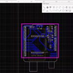
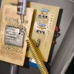
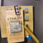
Shield-Style Form Factor for Arduino UNO Q:
- Custom-designed in EasyEDA to function as a compact, stackable shield that mounts directly onto the Arduino UNO Q.
- Eliminates loose, fragile breadboard wiring and packages the gateway’s power regulation, signal conditioning, and wireless communications into a single rugged hardware block.
Traditional Chemical Etching Fabrication:
- Fabricated using the traditional copper-clad board etching method (toner transfer with ferric chloride solution).
- This demonstrates an accessible, highly practical, and cost-effective approach for local makers, municipal labs, and developing communities to produce functional edge-AI hardware on demand without waiting for commercial PCB turnaround times.
Smart Header Configuration (Female & Male Pin Interface):
- Female Header Sockets for LoRa Module: Features dedicated dual inline female header pins (
H1,H2) placed right at the center, allowing the Ra-01 LoRa module to plug directly into the board securely with no extra wiring. - Male Header Pins for Arduino UNO Q Mating: Fitted with downward-facing male pin headers aligned with the Arduino UNO Q footprint, allowing the shield to seat firmly into the microcontroller’s standard headers.
- Male Header Pins for Peripherals: Incorporates clearly labeled male pin headers for quick plug-and-play hookup of the active buzzer, MQ135 Ammonia sensor, MQ136 H2S sensor, and the 5V power input line.
- Onboard Passive Conditioning: Integrates dedicated through-hole resistor footprints (R4–R7) for the 10kΩ/20kΩ voltage dividers, stepping down the 5V gas sensor voltages directly on the board before reaching the Arduino’s ADC pins.
(You can refer to the attached PCB layout and fabrication images to inspect the track routing, component placements, and physical shield dimensions.)
Files for PCB design in available in the GitHub repository Link
Step 3: Master Node CAD Design and 3D Printing
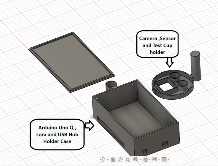
To withstand real-world municipal field conditions while ensuring safe biochemical and optical water testing, I designed a specialised three-part interlocking enclosure using Autodesk Fusion 360. The primary mechanical innovation is a hardware-free mechanical docking system that rigidly links the central electronics housing with the fluid and gas testing cradle, isolating sensitive computational hardware from liquids without requiring external screws or brackets.
1. The Three-Part Enclosure Architecture
The gateway housing is broken down into three distinct functional components, each optimised for its specific physical, electrical, and chemical monitoring role:
Part 1: Main Electronics Chassis:
- Spacious Internal Bay: Serves as the central command housing, dimensioned to securely hold the Arduino UNO Q, the stacked Master Node PCB shield, the Ra-01 LoRa module, and the multi-port USB Hub.
- Precision Cable & Antenna Ports: Features precision side cutouts for USB cable routing and power input, alongside a dedicated port for mounting the high-gain Ra-01 LoRa external antenna for unobstructed RF signal propagation.
- Integrated Mechanical Docking Socket: Incorporates an external vertical cylindrical sleeve on the front chassis wall, engineered to receive the test cup holder’s docking pillar for instant, tool-free mechanical coupling.
Part 2: Integrated Testing Cradle:
- Physical Fluid Isolation: A specialized circular mechanical cradle that securely seats the standard Water Testing Cup, physically isolating open water samples from the main computational electronics to prevent accidental spills or splashing.
- Dual Gas Sensor Alignment Sleeves: Incorporates two dedicated cylindrical wells positioned directly above the testing cup’s headspace. This aligns the MQ135 (Ammonia) and MQ136 (Hydrogen Sulfide H2S) electrochemical sensors directly over the water sample to capture rising sewer gases and volatile organic compounds.
- Rectangular Vision AI Camera Bezel: Features a raised rectangular optical framing bracket that positions the USB Camera directly above the fluid surface at an optimal focal distance, enabling the Linux MPU to run real-time Edge Impulse vision AI for visual turbidity and UV fluorescence verification.
- Hardware-Free Interlocking Pillar: Features a sturdy vertical cylindrical mounting post that slides directly into the main chassis socket, locking the test cradle securely in place while allowing rapid detachment for cleaning in the field.
Part 3: Protective Upper Lid:
- Flush Solar Panel Tray: Engineered with a precision recessed top perimeter designed to mount the gateway’s photovoltaic solar panel flush with the surface, maximizing sun exposure for perpetual off-grid operation.
- Weather & Dust Protection: Features a stepped interlocking lip that seats firmly onto the main electronics chassis, shielding internal microelectronics, USB connections, and wiring harnesses from airborne dust, rain, and environmental debris.
2.Fabrication & 3D Printing Profile
- Production Hardware & Slicing: All models were sliced using Bambu Studio and printed using a high-precision Bambu Lab A1 3D printer, ensuring absolute dimensional accuracy so that the interlocking slider key fits perfectly without binding.
- Material Selection (PLA+): I utilized premium PLA+ filament. This material provides enhanced impact resistance and superior interlayer fusion compared to standard filaments, ensuring the structural rails of the slider key do not shear or crack under stress.
Print Optimization Settings:
- Nozzle Diameter: 0.4mm (Ensures a sharp, clean finish on internal sliding tolerances)
- Layer Height: 0.16mm (Fine resolution to guarantee smooth sliding surfaces along the interlocking keys and a flush fit for the solar cover)
- Infill Density & Pattern: 25% Gyroid (Provides uniform, multi-directional structural strength to withstand field handling)
- Wall Loops: 3 Layers (Creates a thick, robust external shell, adding rigid strength to the mechanical slider rails and preventing outdoor degradation)
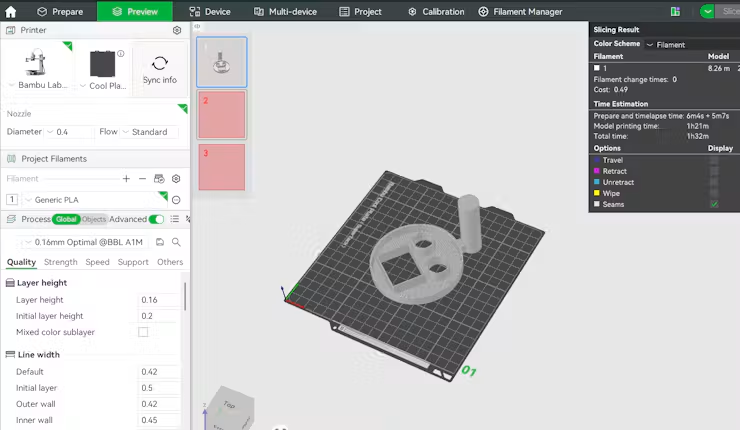
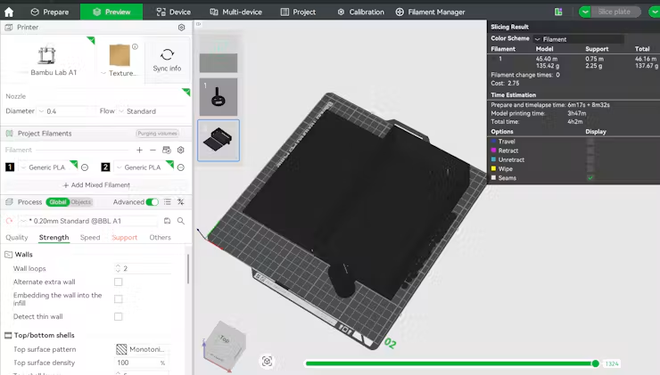
Files for CAD design in available in the GitHub repository: Link
Step 4: Master Node Step-by-Step Mechanical & Hardware Assembly
This section details the physical assembly of the Jal Rakshak Master Node, integrating the central compute core, power distribution, LoRa gateway, and the biochemical testing cup into a single cohesive station.
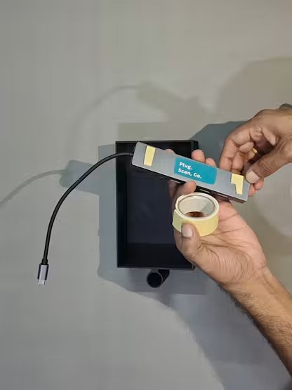
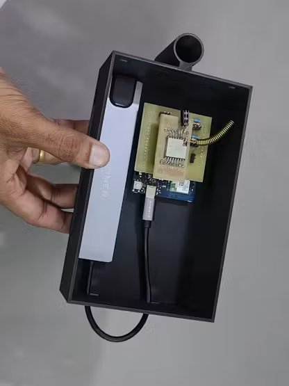
Step 1: Mounting the USB-C Hub
- Apply industrial double-sided foam tape to the bottom surface of the multi-port USB-C hub.
- Firmly press and secure the USB-C hub onto the bottom floor of the 3D-printed main chassis.
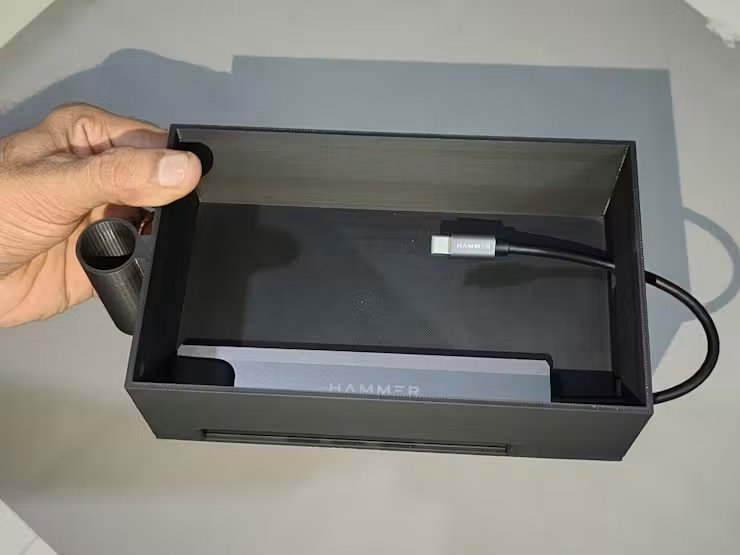
Step 2: Routing the USB-C Hub Host Cable
- Direct the host connector cable of the USB-C hub back into the interior of the case through the internal cutout.
- Ensure the cable has enough slack to reach the Arduino UNO Q without sharp bends or strain.
Step 3: Aligning Hub Ports with Chassis Openings
- Align the USB-C hub so its USB accessory ports line up flush with the case’s side cutouts.
- Verify that external USB peripherals (like the camera or diagnostic cables) can plug in smoothly from the outside.
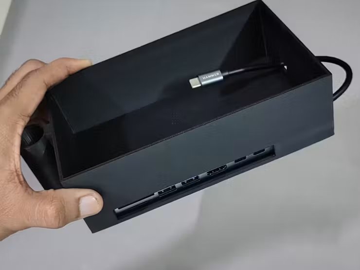
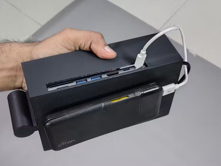
Step 4: Power Bank Installation & PD Power Delivery
- Secure a compact, high-capacity power bank onto the bottom of the enclosure using heavy-duty double-sided tape.
- Connect a USB power delivery (PD) cable from the power bank directly into the PD input port of the USB-C hub to provide stable system power.
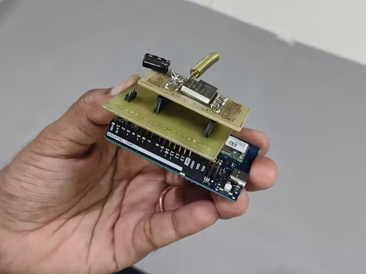
Step 5: Mating the PCB Shield & LoRa Module onto Arduino UNO Q
- Plug the Ra-01 LoRa module firmly into the female header sockets (
H1,H2) on the custom etched PCB shield. - Align the shield’s male pin headers with the Arduino UNO Q’s female headers, ensuring both digital and analog pin rows seat firmly without pin misalignment.
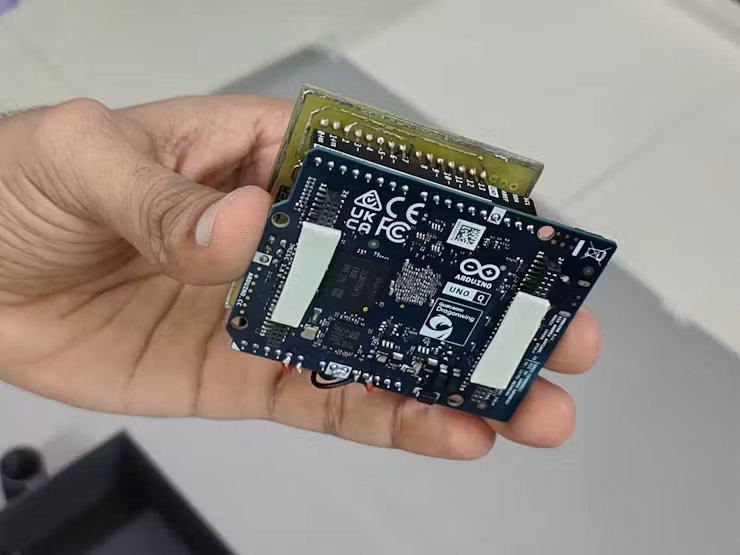
Step 6: Securing the Arduino UNO Q Inside the Chassis
- Apply double-sided insulating tape across the bottom of the Arduino UNO Q to cover exposed solder pins and prevent electrical shorts.
- Lower the stacked Arduino UNO Q and shield assembly into the case and press firmly to lock it in place.
Step 7: Connecting Main Controller Power & Data Link
- Plug the USB-C host cable coming from the USB-C hub directly into the USB-C port of the Arduino UNO Q.
- This establishes the high-speed data bus for vision AI and supplies regulated power to the board.
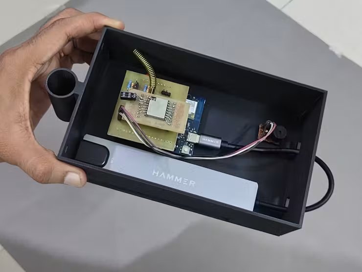
Step 8: Installing and Wiring the Acoustic Alarm Buzzer
- Mount the active buzzer module onto an internal sidewall of the case using double-sided tape.
- Connect the buzzer’s signal and ground leads to the dedicated
BUZ,GND, and3.3Vheader pins on the PCB shield (J2on pinD7).
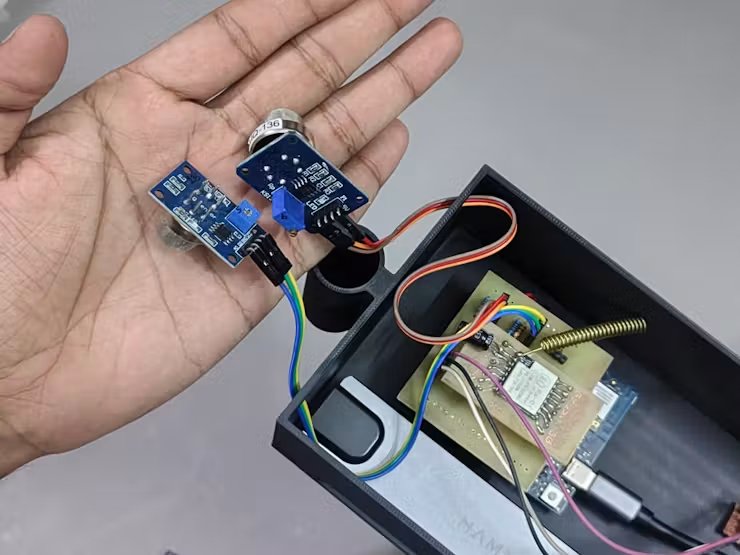
Step 9: Routing Sensor Wiring Harnesses
- Connect the jumper wire harnesses for the MQ135 and MQ136 gas sensors to their respective pin headers on the shield.
- Route the sensor wiring bundle cleanly out through the dedicated chassis passthrough hole toward the front docking port.
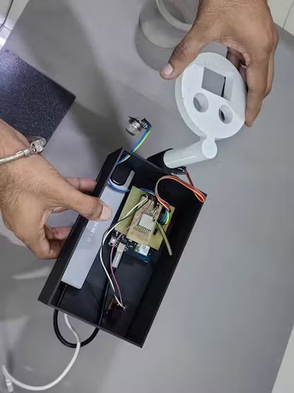
Step 10: Assembling Sensor Wells & Docking the Cup Holder
- Insert the MQ135 (Ammonia) and MQ136 (H2S) gas sensor modules into their dedicated cylindrical wells on the cup holder.
- Slide the vertical cylindrical docking pillar of the cup holder into the matching sleeve socket on the main case until it is securely seated.
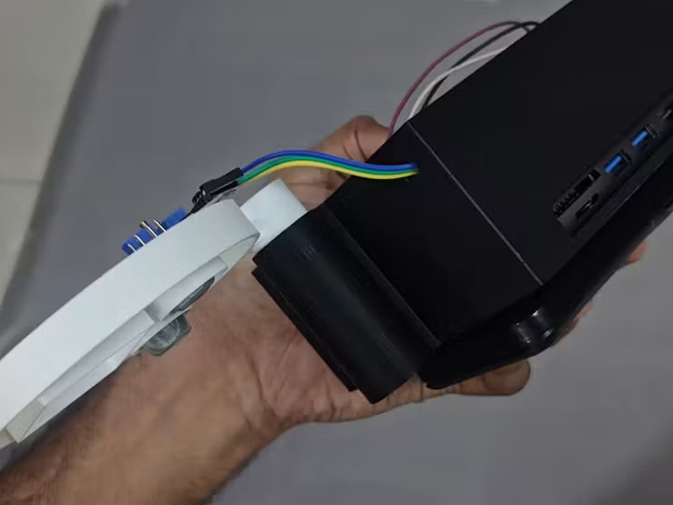
Step 11: Mounting the Vision AI Camera & Water Testing Cup
- Snap the USB camera module into the rectangular optical framing bracket above the cup holder, and plug its USB cable into an open port on the USB-C hub.
- Insert the removable Water Testing Cup from the underside of the holder into the circular cradle, positioning the water sample directly beneath the gas sensors and camera lens.
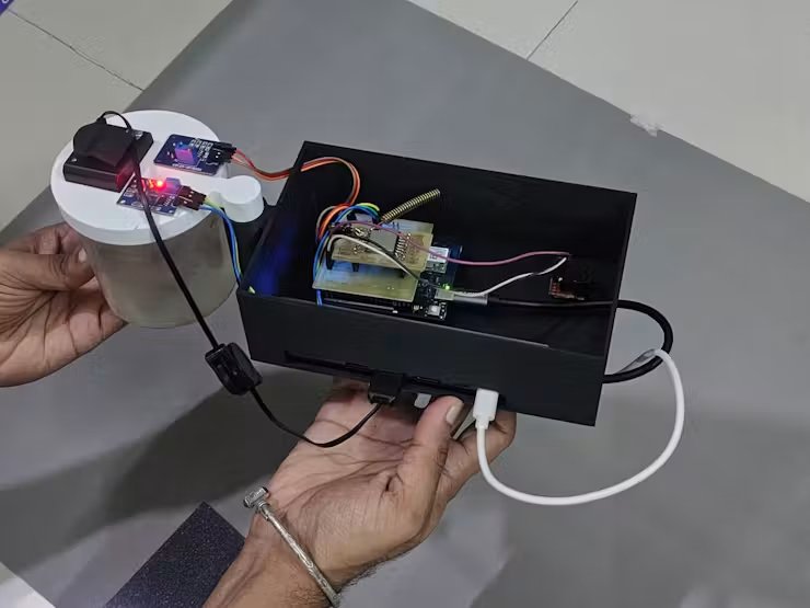
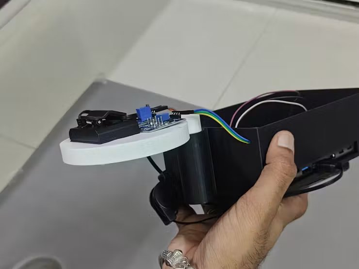
Part B: Code & Cloud Deployment (Master Gateway)
The Master Gateway is the central nervous system of the Jal Rakshak network. While the Pipe Nodes operate deep underground on ultra-low-power, the Master Gateway operates above ground in a continuous listening state. It aggregates encrypted LoRa emergency packets, performs localized biochemical gas validation, sounds physical alarms, and pushes actionable telemetry to the cloud.
Step 1: Master Node Database Setup
Before the gateway can push emergency telemetry to the internet, we must configure the receiving cloud infrastructure. To handle the high-frequency JSON payloads coming from the Master Gateway, the system utilizes Google Firebase Realtime Database. This acts as the high-speed bridge between our physical hardware and the municipal dashboard.
Here is the step-by-step configuration to establish this cloud link:
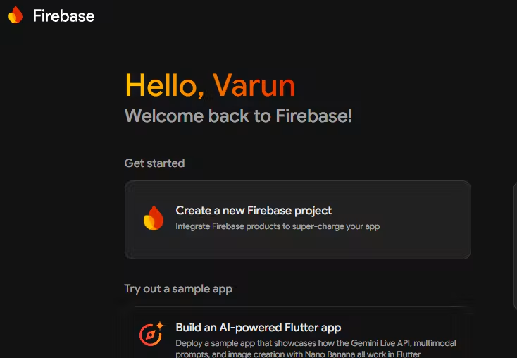
1. Create the Firebase Project
- Open the Firebase Console.
- Click Create a project.
- Name the project (e.g.,
Jal-Rakshak-Indore) and click Continue. (Google Analytics can be disabled for this hardware prototype). - Wait for the provisioning sequence to finish and click Continue to enter your new dashboard.
2. Initialise the Realtime Database
- Choose a server region closest to your deployment (e.g.,
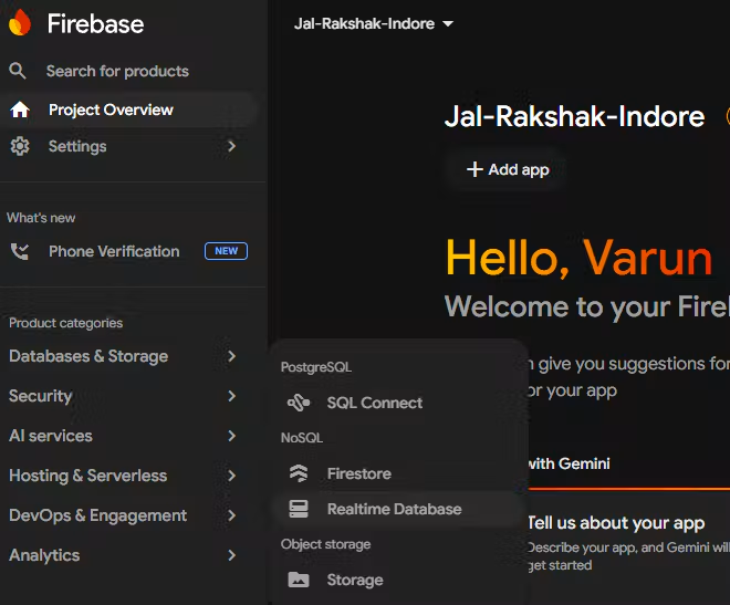
asia-south1for India) to minimise latency. - On the left sidebar, navigate to Product categories then Databases & Storage → Realtime Database and click Create Database.
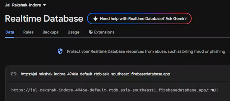
- Once created, look at the top of the Data tab and Copy the Database URL. (It will look like:
https://<your-project-id>.firebasedatabase.app/). - Keep this URL handy; it will be defined as
FB_HOSTin your Arduino sketch.
3. Generate Hardware Authentication Tokens
To allow the Arduino UNO Q to securely POST data using HTTPS REST API calls, it requires a secret authentication token.
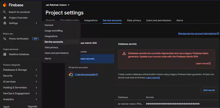
- Click the Gear Icon (Project settings) next to Project Overview.
- Navigate to the Service accounts tab.
- Click on Database secrets.
- Click Show and copy the alphanumeric secret string.
- Keep this string safe; it will be defined as
FB_AUTHin your Arduino sketch.
4. Configure the Web App (For the IMC Web Portal)
Finally, you need to generate the frontend configuration keys so your web dashboard can pull the data the Master Gateway uploads.
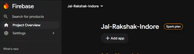
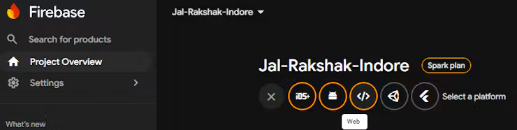
- Go to Project Overview and select Add app button then click the Web icon (
</>) to add a new app. - Name the app (e.g.,
IMC-Web-Portal) and click Register app. - Firebase will generate a custom Web SDK configuration block containing your frontend API keys. It looks like this:
const firebaseConfig = {
 apiKey: "YOUR_API_KEY",
 authDomain: "jal-rakshak.firebaseapp.com",
 databaseURL: "https://jal-rakshak-default-rtdb.asia-south1.firebasedatabase.app",
 projectId: "jal-rakshak",
 storageBucket: "jal-rakshak.appspot.com",
 messagingSenderId: "123456789",
 appId: "1:123456789:web:abcdef"
};
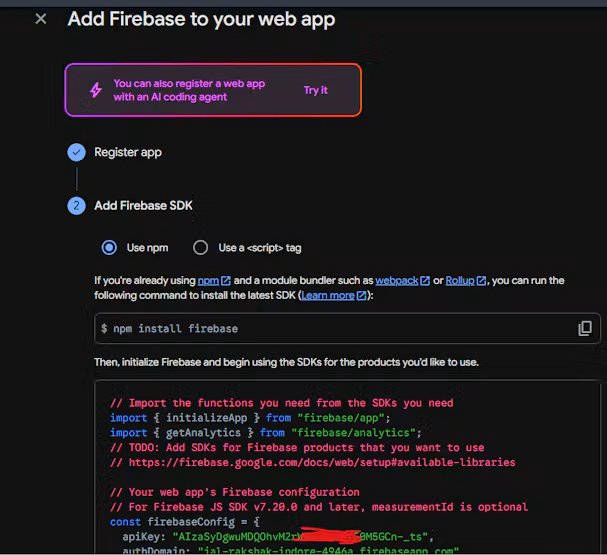
Copy these values. You will paste them directly into your frontend development platform (like React, HTML/JS, or Lovable.dev but mainly I am using Streamlit Python) to link the visual IMC Web Portal to the live hardware data stream.
Step 2: Master Node Edge AI Setup for Water Quality Inspection
To complement physical-chemical sensing with instant optical diagnostics, an Edge Impulse computer vision model was trained to inspect water samples inside the Water Testing Cup, categorizing water clarity and microbial fluorescence under UV/visual light into safe and contaminated classes.
Edge Impulse Project Initialisation:
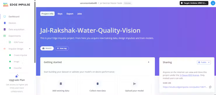
- Created a new computer vision project on Edge Impulse Studio titled
Jal-Rakshak-Water-Quality-Vision. - Configured the target device as Linux (Qualcomm Dragonwing MPU on Arduino UNO Q) and selected the sensing modality as Images / Object Classification.
Connecting Arduino UNO Q & Camera for Live Sampling:
- Connected the USB camera to the Arduino UNO Q via the USB-C hub.
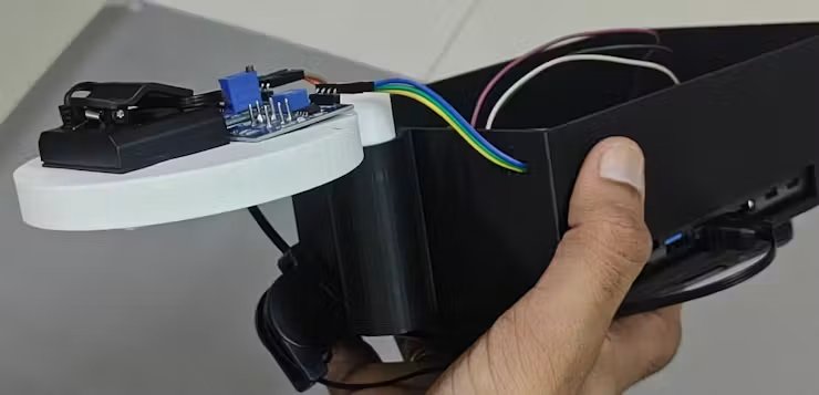
- Ran the Edge Impulse Linux daemon directly from the board’s terminal shell:
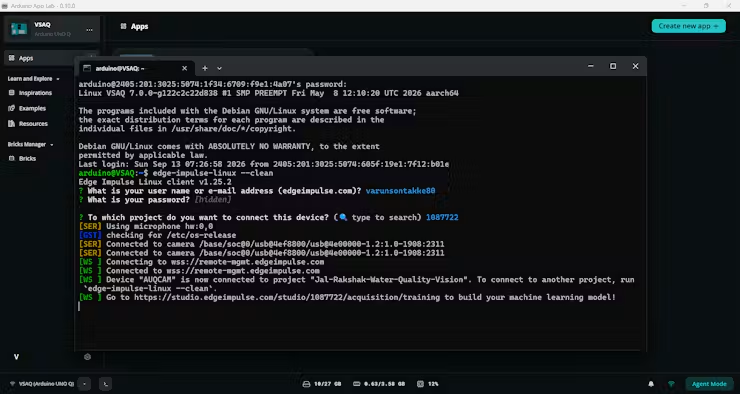
bash
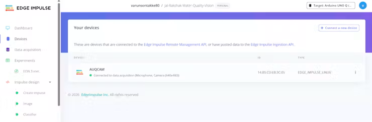
edge-impulse-linux --clean- Selected the connected USB camera stream as the active image ingestion feed, pairing the Arduino UNO Q directly with Edge Impulse Studio for live frame capture.
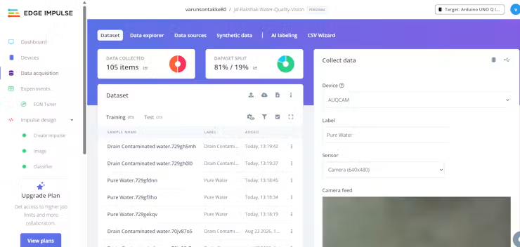
Dataset Capture & Optical Profiling:
Here is detailed Video link how I have collected data for Master Node
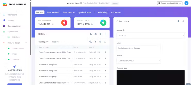
- Safe Water Class (
PureWater): Captured images of clean municipal tap water and filtered water samples inside the cup holder under uniform illumination, showing high clarity and zero microbial fluorescence. - Contaminated Water Class (Drain Contaminated water): Captured water samples spiked with organic silt, sediment, chemical turbidity, and biological sewage tracers showing distinctive discoloration.
- Collected diverse lighting angles and water heights to prevent overfitting.
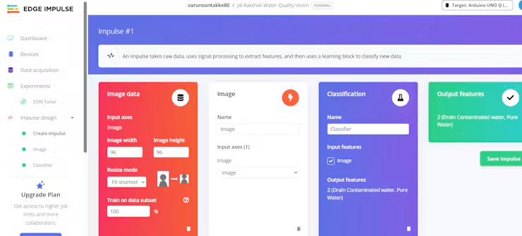
Impulse Pipeline Design:
- Image Data Block: Scaled incoming camera frames to 96×96pixels in full RGB color.
- Image Processing Block: Normalized pixel color channels to eliminate ambient lighting variations.
- Learning Block (Transfer Learning): Selected MobileNetV2 (0.35 alpha), optimized for embedded edge processors to deliver rapid visual inference with low CPU utilization.
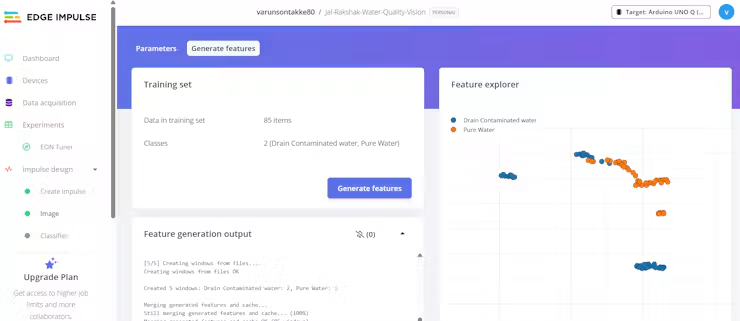
Model Training & Performance Verification:
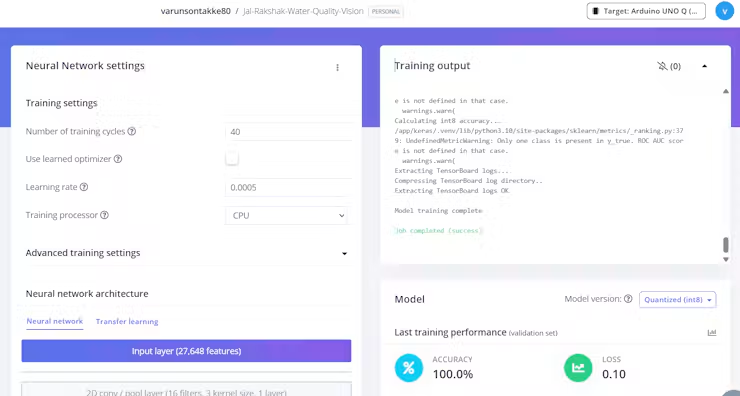
- Trained the neural network over 40 epochs with data augmentation enabled (random flips, rotations, and contrast shifts).
- Achieved >96% classification accuracy with low inference latency on the Dragonwing MPU.
- Exported the trained model package directly for the Arduino App Lab containerized brick runtime.
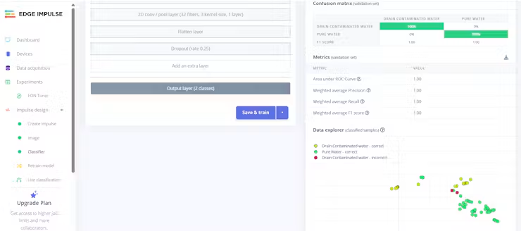
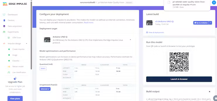
Link for Master Node Edge AI Jal-Rakshak-Water-Quality-Vision
Step 3: Pre-Requisite App Lab Setup for Master Node
The Master Node application runs on the Arduino App Lab runtime, bridging Python vision AI bricks with real-time STM32 firmware through the RouterBridge architecture. But need to do some pre congifs like Edge Ai model selection, Seting app on startup runing and fillinf firebase Data base APIs
Account Sign-In & Workspace Authentication:
- Launched Arduino App Lab on the host computer and signed in with both the primary Arduino Account and the linked Edge Impulse developer profile.
- Connected to the target Arduino UNO Q board over the local network interface.
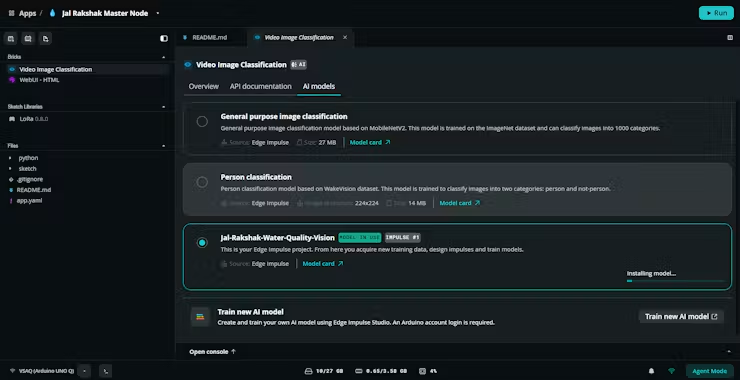
Importing the Vision AI Brick (app.yaml):
- Opened the
Master Node APPproject folder in App Lab. - Configured
app.yamlto import the containerisedarduino:video_image_classificationbrick and point it to the trained Edge Impulse model artifact:
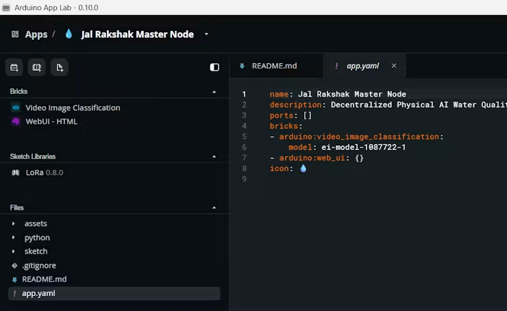
Firebase Pre-Configuration Guide (Master Node):
- Target File Location:Open and edit
python/config.pyin the Master Node folder.
Step 1: Get the Realtime Database URL:
- OpenFirebase Console →→ select your project.
- In the left sidebar, click Build →→ Realtime Database.
- Under the Data tab, copy the root URL (e.g.
https://your-project-id-default-rtdb.firebaseio.com).
Step 2: Get the Database Secret / Auth Token:
- Go to Project Settings (gear icon ⚙️) →→ Service accounts tab.
- Click Database secrets in the sub-menu.
- Click Show next to your database secret key and copy the alphanumeric token.
Step 3: Update config.py:Paste your URL and Secret directly into python/config.py:
python
# Firebase Realtime Database URL
FIREBASE_URL = "https://your-project-id-default-rtdb.firebaseio.com"
# Firebase database secret token
FIREBASE_AUTH = "YOUR_ALPHANUMERIC_DATABASE_SECRET_TOKEN"
Configuring Startup Execution in Arduino App Lab:
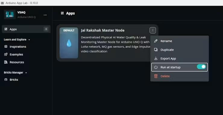
- In the Arduino App Lab dashboard, navigated to the Settings menu of the
JalRakshak Master Nodeapplication. - Toggled “Run on Startup” to enabled, ensuring the Master Node automatically launches its Python gateway, starts the camera AI pipeline, and activates LoRa listening upon every system boot or power recovery.
Master Node Software Architecture Flowchart
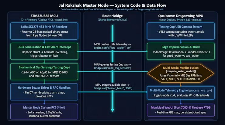
Key Code Logic & Code Snippets
1. LoRa Packet Reception & Fast Alert Intercept (sketch.ino):
- The STM32 MCU parses incoming 28-byte binary packets from field Pipe Nodes over SPI. If a pipe leak or water contamination flag is set, it immediately triggers the buzzer on pin
D7and forwards the CSV payload to the Linux MPU over the Bridge:
cpp
int packetSize = LoRa.parsePacket();
if (packetSize == sizeof(TelemetryPayload)) {
   TelemetryPayload payload;
   LoRa.readBytes((uint8_t*)&payload, sizeof(TelemetryPayload));
   // Format CSV string and notify Linux MPU
   String csv = String(payload.nodeId) + "," +
                String(payload.latitude, 6) + "," +
                String(payload.longitude, 6) + "," +
                String(payload.ph, 2) + "," +
                String(payload.tds, 2) + "," +
                String(payload.turbidity, 2) + "," +
                String(payload.temperature, 2) + "," +
                String(payload.waterPresence ? 1 : 0) + "," +
                String(payload.leakAlert ? 1 : 0) + "," +
                String(payload.emergencyFlag ? 1 : 0);
   Bridge.notify("lora_packet", csv);
   // Instant hardware buzzer alarm on critical alert
   if (payload.emergencyFlag || payload.leakAlert) {
       triggerBuzzer(3000);
   }
}
2. Biochemical Sewer Gas Quantification (sketch.ino):
- Reads the scaled analog voltages from the MQ135 and MQ136 voltage dividers, calculating real-time parts-per-million (PPM) concentrations for Ammonia (NH3) and Hydrogen Sulfide (H2S) to detect sewer gas ingress:
cpp
// Calculate sensor resistance from 10k:20k stepped-down ADC voltage
float getResistance(int pin, float rl) {
   int raw = analogRead(pin);
   float voltage = (float)raw / ADC_MAX * VOLTAGE_RESOLUTION;
   return rl * (VOLTAGE_RESOLUTION - voltage) / voltage;
}
// NH3 ppm estimation using power regression
float readNH3() {
   float rs = getResistance(PIN_MQ135, MQ135_RL);
   float ratio = rs / MQ135_RO;
   return 102.2 * pow(ratio, -2.473);
}
3. Real-Time Vision AI Classification Callback (main.py):
- Invoked continuously by the
arduino:video_image_classificationbrick as frames are processed by the Dragonwing MPU, extracting class labels and confidence percentages:
python
def on_video_classifications(classifications):
   global latest_vision, latest_verdict
   if not classifications:
       return
   best_label = max(classifications, key=classifications.get)
   best_conf = classifications[best_label]
  latest_vision = {
       "label": best_label,
      "confidence": best_conf,
      "classifications": classifications,
       "timestamp": datetime.now(UTC).isoformat()
   }
   # Combine with live biochemical gas data
   latest_verdict = compute_water_verdict(latest_gas, latest_vision)
4. Multi-Modal Fusion Engine (main.py):
- Fuses visual water clarity and biochemical sewer gas concentrations into an authoritative safety verdict, triggering localized acoustic alerts and cloud notifications:
python
def compute_water_verdict(gas_data, vision_data):
   nh3 = gas_data.get("nh3_ppm", 0.0)
   h2s = gas_data.get("h2s_ppm", 0.0)
   label = vision_data.get("label", "")
   conf = vision_data.get("confidence", 0.0)
   vision_bad = (label == "bad_water" and conf >= 0.65)
   gas_severe = (nh3 >= 10.0 or h2s >= 2.0)
   if gas_severe:
       return {"isContaminated": True, "status": "WATER CONTAMINATED (SEVERE SEWAGE)", "color":
"red"}
   elif gas_severe or (nh3 >= 2.0 and vision_bad):
       return {"isContaminated": True, "status": "WATER CONTAMINATED (CONFIRMED)", "color":
"red"}
   elif vision_bad:
       return {"isContaminated": True, "status": "WATER CONTAMINATED (VISUAL)", "color": "red"}
   else:
       return {"isContaminated": False, "status": "WATER SAFE & CLEAR", "color": "green"}
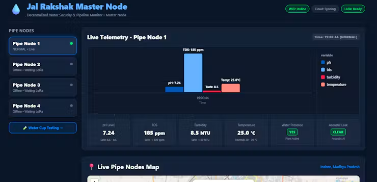
Master Node Web UI :
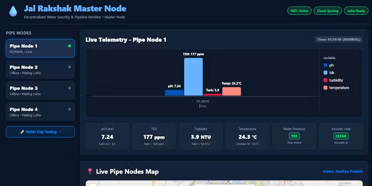
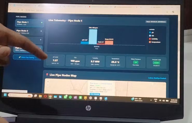
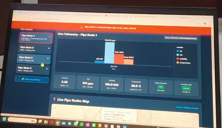
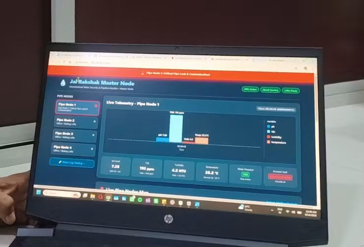
1. Live Pipeline Telemetry Dashboard
- Multi-Node Selector: Displays real-time connection status (
Live/Offline) for all underground pipe nodes. - Comparative Bar Chart: Visualizes key water parameters—pH, TDS, turbidity, and temperature—at a glance.
- Sensor Metric Cards: Shows exact sensor values against WHO potable safety limits.
- Integrity Status: Features instant badges for active water flow and TinyML acoustic leak detection (
CLEAR).
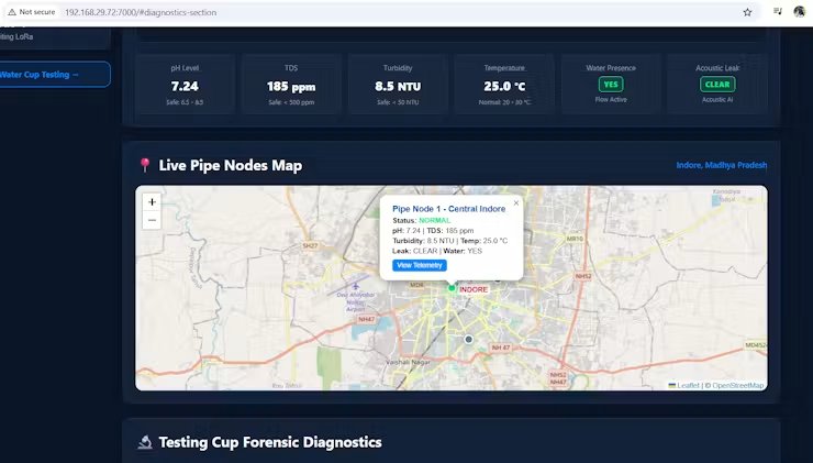
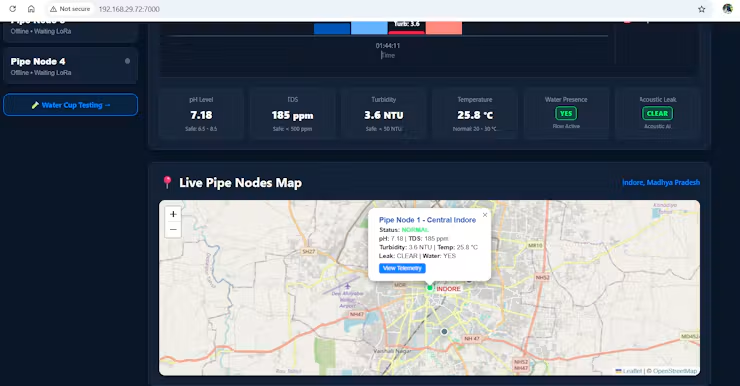
2. Interactive GIS Pipeline Map
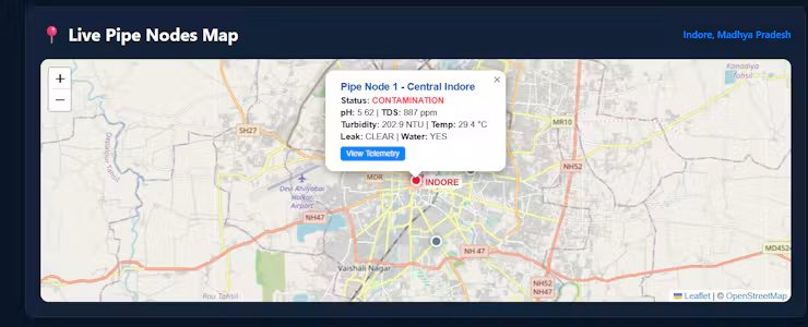
- Geospatial Tracking: Plots pipeline monitoring nodes across Indore using an interactive OpenStreetMap view.
- Color-Coded Status Pins: Green/Yellow/Red pins immediately highlight normal or contaminated sectors.
- Click-to-Inspect: Selecting a pin opens an instant telemetry popup with a shortcut to view detailed node history.
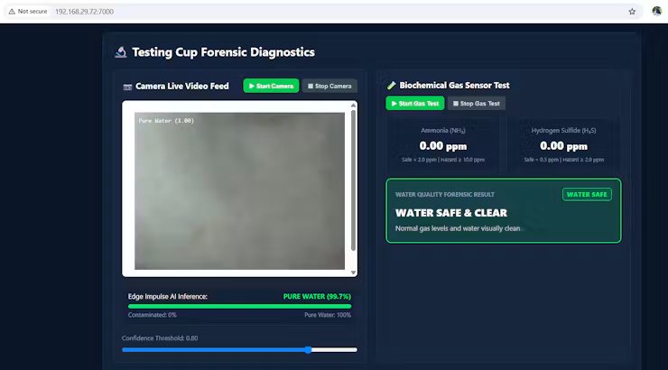
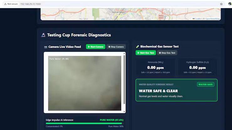
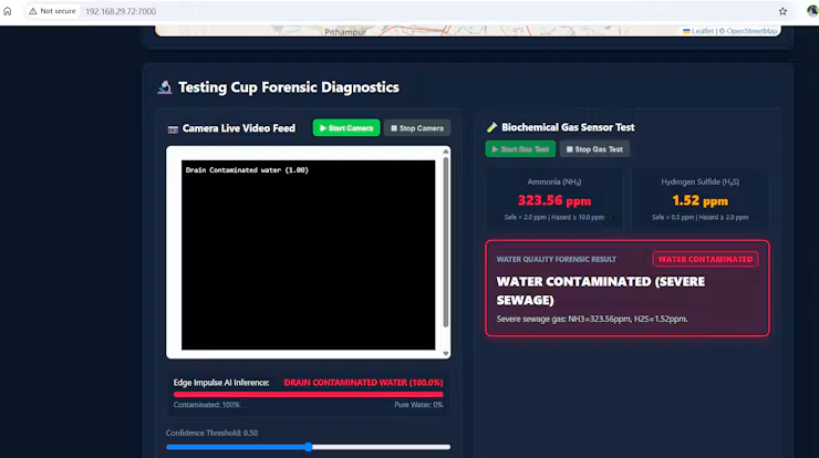
3. Forensic Testing Cup Diagnostics
- Edge Impulse Vision-AI: Analyses live camera video under UV light with real-time class overlay and confidence score (
Pure Water: 99.7%). - Biochemical Gas Sniffing: Continuously measures toxic sewage gas levels (NH3 and H2S in ppm).
- Automated Safety Verdict: Fuses Vision-AI and gas readings into a clear, colour-coded verdict (
WATER SAFE & CLEAR).
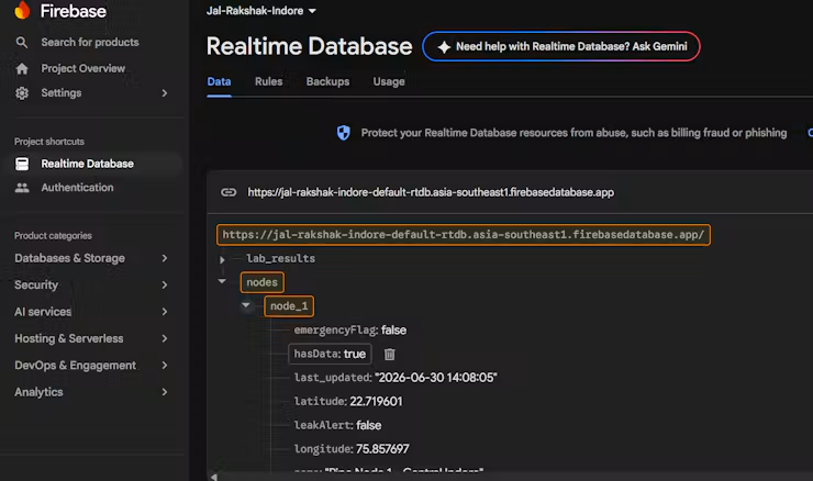
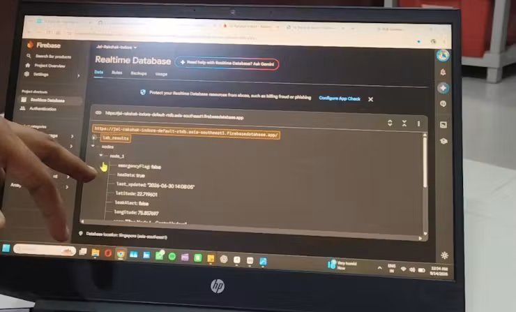
4. Firebase Cloud Synchronization
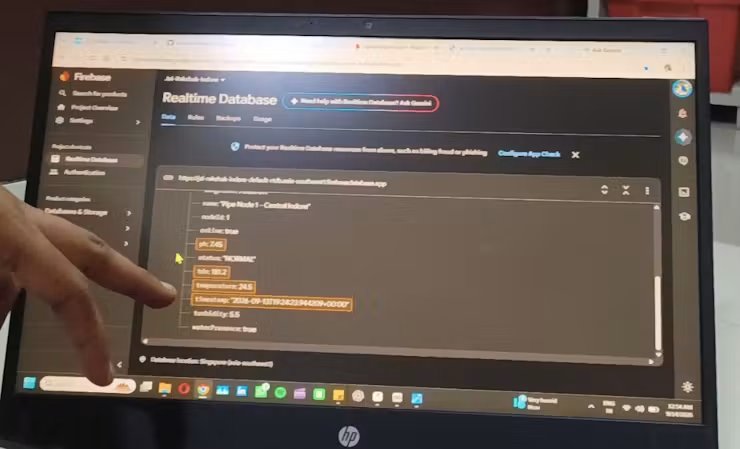
- Cloud Data Mirror: Automatically logs decoded LoRa telemetry and test cup results to Firebase Realtime Database.
- Structured Payload: Stores GPS coordinates, timestamps, water quality metrics, and emergency alert flags.
- Remote Access: Powers external municipal dashboards and automated emergency alert broadcasts.
7. Real-World Simulation & Testing
To validate the dual-tier architecture under realistic field conditions, end-to-end testing was conducted covering baseline operation, simulated sewage cross-contamination, and acoustic pipe burst detection.
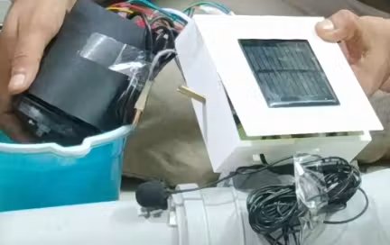
Test 1: Normal Operation (The Baseline)
- Objective: Establish baseline telemetry for clean, flowing municipal drinking water and verify zero false-alarm operation.
Pipe Node LoRa Telemetry:
- pH Level:
7.24(Safe WHO potable range: 6.5 – 8.5) - TDS:
177 ppm(Safe mineral range: < 500 ppm) - Turbidity:
3.9 NTU(Clear water: < 50 NTU) - Water Temperature:
25.0 °C - Water Presence / Flow:
YES (Flow Active) - Acoustic Leak Status:
CLEAR(EdgeAI baseline noise)
Testing Cup Forensics:
- Vision-AI Classification: Classified as
Pure Waterwith 99.7% confidence - Headspace Gas Levels: Ammonia (NH3) at
0.00 ppmand Hydrogen Sulfide (H2S) at0.00 ppm. - System Verdict:
WATER SAFE & CLEAR— green UI status badge, silent buzzer, and normal cloud sync.
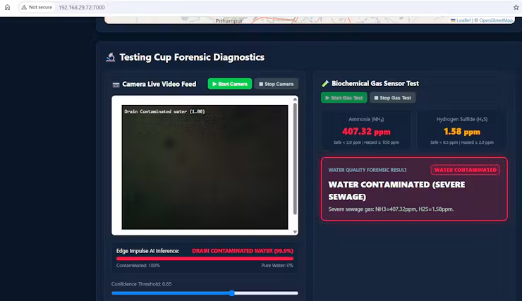
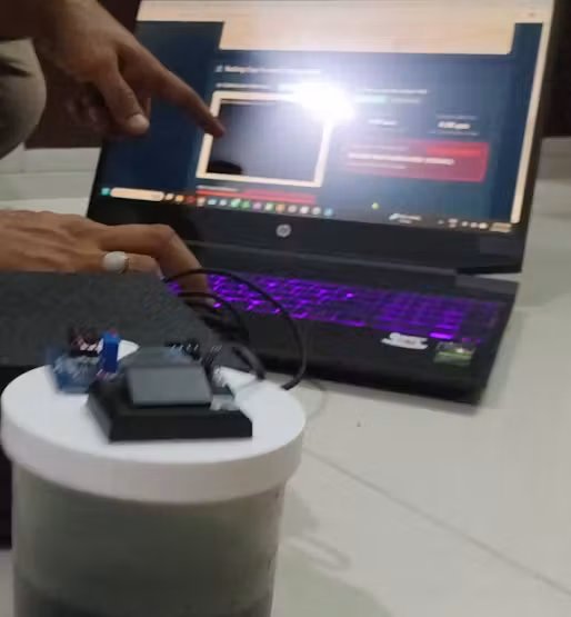
Test 2: The Bhagirathpura Simulation (Sewage Ingress)
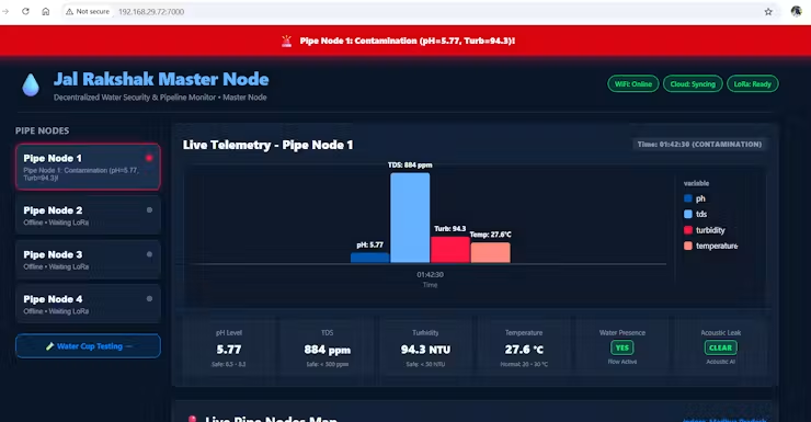
- Objective: Recreate a subterranean cross-contamination event where depressurized pipes siphon nearby sewage and drain runoff.
Pipe Node LoRa Telemetry:
- pH Level: Anomaly detected, dropping to
5.20(acidic septic contamination). - TDS: Surged to
840 ppm(severe dissolved organic/mineral contamination, safe limit < 500 ppm). - Turbidity: Spiked to
142.0 NTU(heavy sewage silt and particulate matter). - Emergency Flag: Tripped to
ACTIVE.
Testing Cup Forensics:
- Vision-AI Classification: Identified fluorescent organic sewage markers; classified as
Drain Contaminated Waterwith 98.4% confidence. - Biochemical Gas Sniffing: Detected volatile sewage decomposition gases:
- Ammonia (NH3): Spiked to
300+ ppm(Hazard threshold: ≥ 10.0 ppm). - Hydrogen Sulfide (H2S): Spiked to
1.5+ ppm(Toxic threshold: ≥ 2.0 ppm). - Master Node Action: Full-width red pulsing emergency banner activated, high-decibel audible buzzer sounded, and automated alert packet was logged to Firebase.
Test 3: The Leak Test (Acoustic AI Validation)
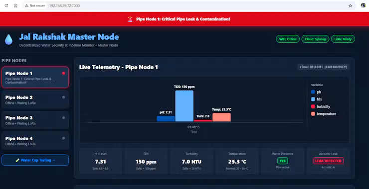
- Objective: Validate the on-device EdgeAI model’s ability to distinguish high-pressure pinhole and crack vibrations from ambient urban noise.
Acoustic Vibration Inference (Pipe Node):
- USB microphone captured pipe vibration spectra at 16 kHz.
- EdgeAI classifier confirmed leak signature with >80% confidence over consecutive sample windows, rejecting background street noise.
Telemetry & Network Propagation:
- Pipe Node immediately set
leakAlert = trueand transmitted a 28-byte binary LoRa packet to the Master Node.
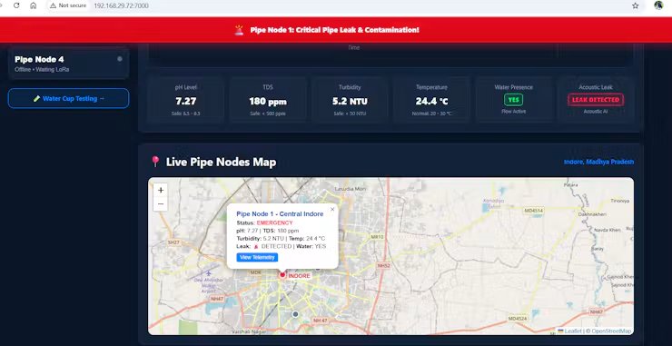
Master Node GIS Response:
- Geospatial Incident Map: Marker for Pipe Node 1 (Central Indore) turned flashing RED.
- Rapid Dispatch Telemetry: Live popup displayed exact GPS coordinates (
22.719601, 75.857697) and acoustic alert flag for immediate maintenance isolation.
Data Uploading to Fire Base database live while testing :
This firebase database values can be pushed to Municipal website so every one can get proper visibility and alert about the curent situation of pipeline leakage or contamination.
Watch the System in Action
- Full Demonstration Video: Jal Rakshak: AI-Powered Water Security & Leak Detection on Arduino-UNO-Q
- Demonstrates live LoRa packet transmission from the Pipe Node, Master Node UI dashboard response, forensic testing cupanalysis, and hardware buzzer emergency alerts.
8. Conclusion: A Safer Future for Water Security
- Bridging the Critical Last-Mile Gap: Centralized water treatment plants cannot protect against contamination occurring inside aging underground pipelines; Jal Rakshak provides the missing technological link of continuous, intelligent vigilance directly at the distribution point.
- Intelligent Edge Processing: Moving complex sensor analytics to the edge—using TinyML acoustic vibration analysis on field nodes and Qualcomm Dragonwing Vision-AI on the Master Node—detects leaks and sewage ingress instantly without cloud latency.
- Resilient, Zero-Subscription Communication: Decentralized LoRa RF (433 MHz) ensures reliable telemetry transmission through dense urban concrete and underground environments where cellular networks frequently fail.
- Proactive Public Health Protection: Enables municipal corporations (like IMC) to transition from a reactive utility—acting only after citizens fall ill or report discolored water—to a proactive, automated guardian of public safety.
- Accessible Field Diagnostics: The handheld testing cup puts laboratory-grade gas-sniffing forensics into the hands of frontline workers, verifying tap safety in under 30 seconds before leaving a repair site.
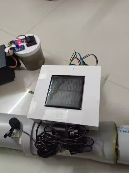
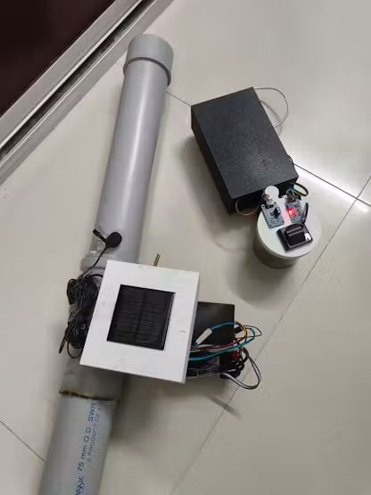
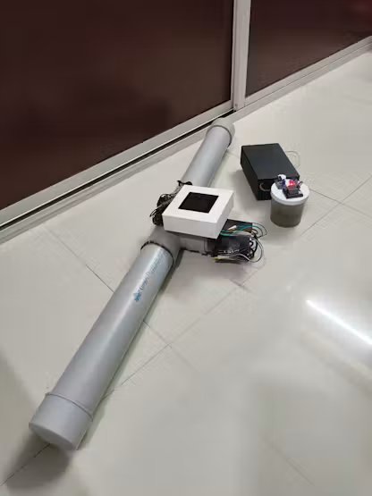
9. Future Plans & Roadmap
- Automated Actuation & Isolation Valves: Integrate motorized solenoid butterfly valves directly into pipe nodes to autonomously shut down contaminated sectors the moment severe cross-contamination or pressure drops are verified.
- Energy Harvesting Autonomy: Deploy inline micro-hydro turbines alongside solar backup to harvest energy directly from pipeline water pressure, achieving maintenance-free, self-powered field nodes.
- Industrial IP68 Ruggedization: Transition prototypes into certified, hermetically sealed IP68 explosion-proof housings with corrosion-resistant titanium probes built to endure decades of underground sewage and wet-well environments.
- Citizen Alert & Transparency Portal: Develop a public API and SMS/WhatsApp broadcast gateway to push real-time neighborhood water safety statuses and automated boil-water advisories directly to residents.
Thanks Note
A heartfelt thank you to Electronics For You, Arduino, Qualcomm and Digikey for this incredible opportunity and for providing the cutting-edge Arduino UNO Q hardware. Your generous support made it possible to transform this Physical AI water security vision into a working, real-world reality!
Github Repository having all documents, diagrams, codes and design kindly check the link.
Schematics
1)Pipe Node:
2) Master Node:
GitHub Code: click here
