




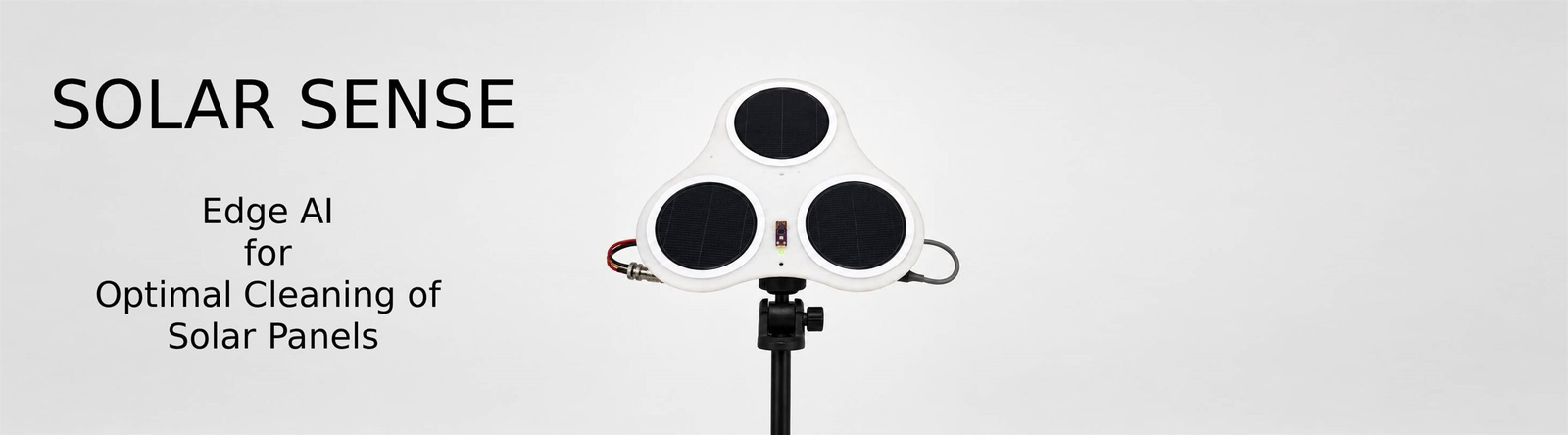
SolarSense: Differential Solar Panel Soiling Detection with LoRa Telemetry and Edge AI. Solar panels lose 15–25% efficiency from dust and soiling, but cleaning is scheduled on a fixed calendar rather than when it is actually needed. The result is panels cleaned too early, wasting labour, or left dirty too long, losing revenue.
The challenge is that panel output drops for many reasons — clouds, haze, low sun angle — not just dirt. You cannot simply watch the power number.
SolarSense solves this by keeping one panel permanently clean as a live reference. Dividing any other panel’s output by the reference cancels out weather completely, because both panels see the same sky at the same instant. The ratio drops only from soiling. An Edge Impulse AI model watches this ratio alongside environmental data — UV, air quality, humidity, and surface temperature — and tells you whether a panel is clean, needs scheduling for cleaning, or needs immediate attention.
Video:
All project files and the final video are in one public folder: SolarSense — shared project folder (Google Drive)
Preface
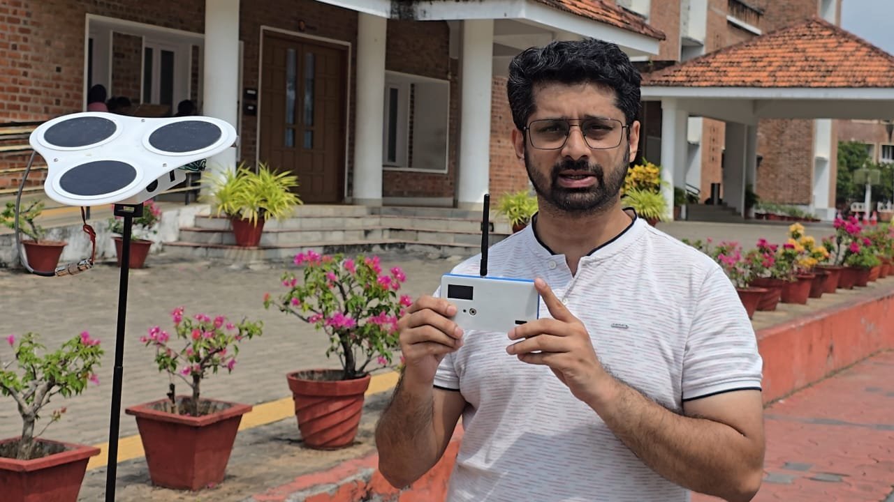
I wrote this report with the judges’ electronics expertise in mind. The hardware is covered at circuit level: the schematic block by block (A7), why each part was chosen, and how the buses are wired and timed. Part B covers the board faults I found and how I traced them. The parts outside electronics — the AI model, the Linux scripts and the mechanical build — are explained in plain terms.
A short, non-technical 5-page summary of the project is provided as a separate document ( SolarSense-Summary.pdf, in the writeup/ folder of the shared folder).
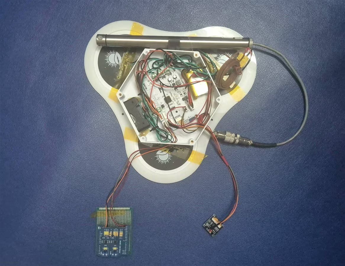
Summary — SolarSense in one minute
SolarSense tells you when a solar panel needs cleaning.
- Three small panels sit side by side. One is kept clean all the time; the other two collect dust. A custom board under the panels measures the current from each panel, plus panel temperature, UV, outdoor humidity and temperature, and air quality.
- Dividing a dusty panel’s output by the clean panel’s output cancels out the weather: both see the same sky, so any difference is dirt.
- The data goes indoors two ways. A CAN cable carries a lot of data, used to train an AI model in Edge Impulse. LoRa radio carries one small packet a minute, used to watch the panels.
- An Arduino UNO Q runs the trained model and sends the result — CLEAN PANEL or NO ACTION — to the screen of a LoRa base station (a Wio Tracker L1).
Status: the PCB, the sensors, CAN data collection and the LoRa link are built and tested. The AI model works in Edge Impulse. Running it live on the UNO Q against LoRa data is built, but so far tested offline only (B11).
How this write-up is organised
- Part A — The Project Explained. What SolarSense is, how it’s built, the components, the schematic block by block, how the code works (with snippets), how to wire it and run it, and the demo. Read this to understand or rebuild it.
- Part B — The Development Journey. How it actually got built: the problems I hit, how I found the cause, and what I still don’t know. Read this to avoid my mistakes.
PART A — THE PROJECT EXPLAINED (Project Explanation Step By Step)
The Component List, Coding Explanation and Configuration, Connection Explanation and Testing sections are inside Part A — A5, A10, A11 and A13.
A1. The Problem
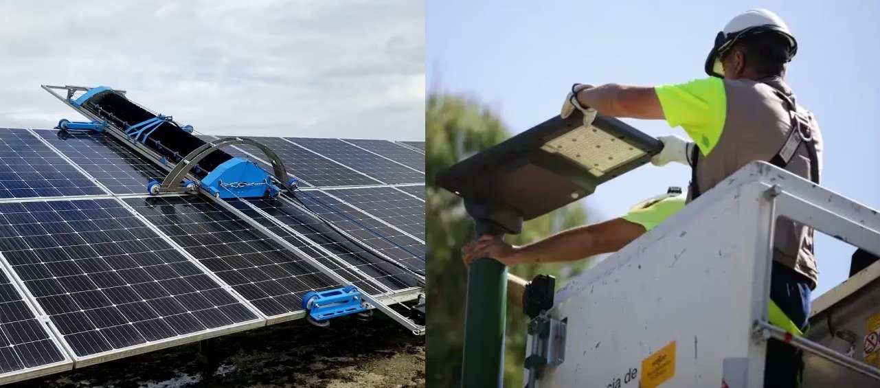
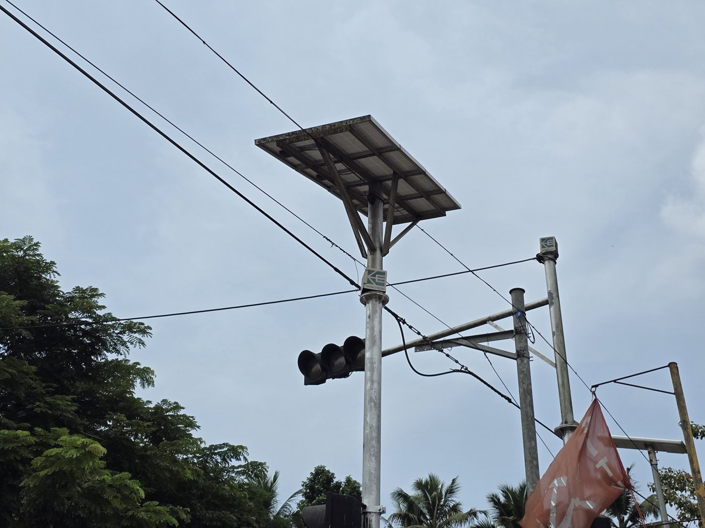
Dust and dirt can cut a solar panel’s output by up to 50%. Big solar farms clean on a fixed schedule, with robots or sprinklers. That doesn’t pay for small installations — a panel on a street lamp, a remote sensor, a home rooftop.
Watching the power output alone doesn’t work either, because a cloud lowers the output just like dust does. Is it dust, or just a cloudy afternoon? So the real question is when to clean. Clean too often and you waste labour; clean too late and you lose energy.
This project is close to my heart. It grew out of my Master’s thesis, where I built a small solar-panel cleaning robot driven by Shape Memory Alloy. SolarSense is the other half of that problem: knowing when cleaning is needed, so the robot (or a person) knows when to act.
A2. The Idea — a Clean Reference Panel
I use three identical 1 W / 5.5 V panels (cheap ones I bought a while back). One of them, P3, is kept clean all the time — it is the reference. All three see the same sky at the same moment, so the clean panel shows what the other two should produce. Divide a test panel’s output by the reference panel’s output, and the weather cancels out. If the ratio drops, the panel is dirty.
soiling ratio (P1) = P1 output / P3 output      P3 = the panel I keep clean
soiling ratio (P2) = P2 output / P3 output
                     1.00 → as clean as the reference
                     0.70 → producing 30% less than it should, under the same sky
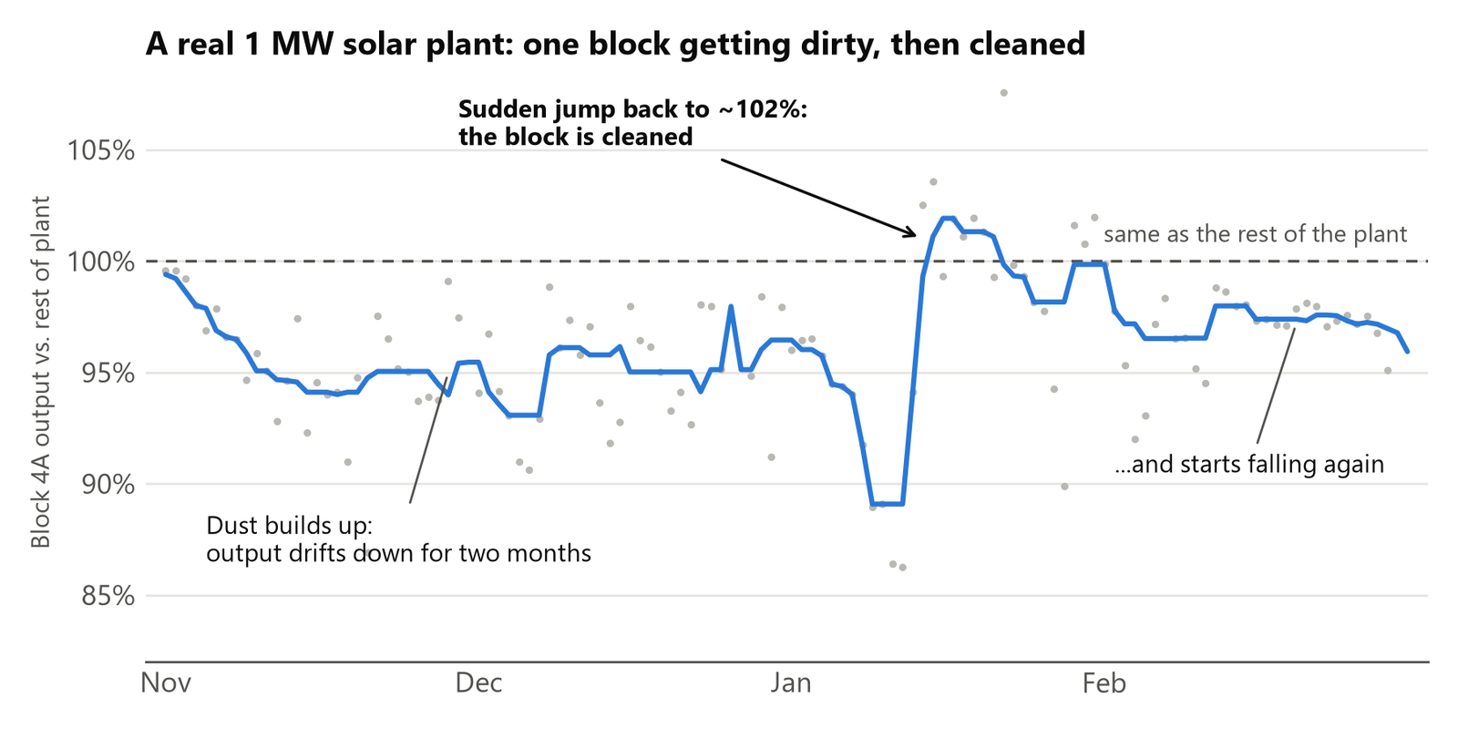
The same idea on a real solar plant. In my Master’s research I worked with daily generation data from IIT Delhi’s 1 MW solar plant: 46 inverters in nine blocks. The plant’s output goes up and down mostly with the weather, so the raw numbers hide soiling. But compare one block with the rest of the plant on the same day, and the weather cancels out — the same trick as P1 ÷ P3. Fig 5 shows one block over four months. Its output drifts down as dust builds up, jumps back suddenly when the block is cleaned, then starts falling again. The data file has no cleaning log, so the cleaning is read from that jump — and that jump is exactly the pattern SolarSense is built to catch automatically.
A ratio alone isn’t the whole story, though. A panel that runs hotter, dust in the air, or humidity on the glass also change the numbers. So the board also measures panel surface temperature, UV, outdoor humidity and temperature, and air quality. An AI model trained in Edge Impulse uses all of these together to decide: clean, soiled or alert.
A3. Two Links, Two Jobs — Why CAN and LoRa?
The board sends its data indoors over two different links, each with a different job.
CAN (wired) — for collecting training data. CAN is the wired bus used in cars and factories. It works reliably over long cables (50 m and more) and checks every message in hardware. To train an AI model I need a lot of data — every sensor, every 5 seconds, for weeks — so I can try different ways of summarising it over time (averages, peaks, different time spans). Every 5 seconds the board sends all its readings as 10 CAN messages at 500 kbit/s. WiFi would be unreliable outdoors and use more power, and LoRa is far too slow for this much data. The CAN data goes to the Arduino UNO Q, which uploads it to Edge Impulse for training.
LoRa (radio) — for deciding when to clean. LoRa is a low-power, long-range radio for small packets. Once the model is trained, I don’t need data every 5 seconds. One small packet a minute (46–72 bytes) with the panel readings is enough. LoRa needs no cable — useful, because I still haven’t run a CAN cable from my terrace into the house — and the board can sleep between packets to save battery.
In short: CAN to learn, LoRa to watch. The same Arduino UNO Q does both jobs. A Wio Tracker L1 receives the LoRa packets and passes them to the UNO Q over a wired serial (UART) link. The UNO Q runs the model and sends the answer back to the Wio Tracker’s screen. It’s a wired UART, not USB, because the UNO Q’s only USB-C port is needed for power. This last step is built but so far tested offline only (B11).
A4. System Architecture
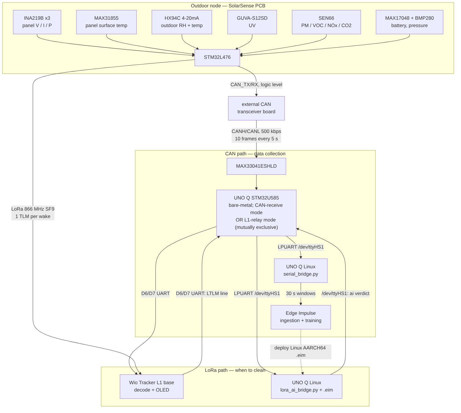
Terms used throughout:
| Term | Meaning |
|---|---|
| CAN | a wired bus used in cars and factories; reliable over long cables |
| LoRa | a low-power, long-range radio for small data packets |
| MPPT | maximum power point tracking — the charger keeps the panels at the voltage where they give the most power |
| UART | a simple wired serial link (one transmit and one receive line) |
| Edge Impulse | an online tool for training small AI models that run on devices |
.eim | an Edge Impulse model packaged as a single program that runs on Linux |
| TLM | the node’s data packet — every sensor reading from one moment |
| LTLM | the base station’s one-line text copy of a TLM, sent to the UNO Q |
| SF | LoRa spreading factor — higher means longer range but slower sending |
| PHY | the radio settings: spreading factor, bandwidth, transmit power |
| Class-A | the node listens only for a short moment right after it sends |
| Reconciliation | the base checks the settings the node reports against the settings it wants, and resends if they differ |
dma (in p1_dma ) | tenths of a milliamp — values travel as whole numbers |
| DNP | “do not populate” — a part drawn on the PCB but left unfitted on purpose |
| STOP2 | the STM32L4’s deep-sleep mode; memory is kept, and the real-time clock wakes it |
| PCM | the protection circuit built into the LiPo battery pack |
| USART / LPUART | the STM32’s serial (UART) ports; LPUART is the low-power one |
| HAL | ST’s hardware library for STM32 peripherals |
| UF2 | a drag-and-drop firmware file for a USB bootloader |
| systemd | Linux’s service manager; it starts programs at boot |
There are four boards:
| Board | Where | Job |
|---|---|---|
| SolarSense PCB (STM32L476) | outdoors, under the panels | reads every sensor; sends CAN every 5 s in data-collection mode, or sends one LoRa packet per wake-up and sleeps in between in power-save mode (A10.1) |
| Arduino UNO Q — STM32U585 side | indoors | receives the CAN messages and joins them into one line of text for Linux |
| Arduino UNO Q — Linux side | indoors | uploads data to Edge Impulse (CAN path); runs the trained .eim model (LoRa path) |
| Wio Tracker L1 (nRF52840 + SX1262) | indoors; UART from itsD6 / D7 to the UNO Q’sD0 / D1 (A11) | LoRa base station: receives the node, sends it settings, shows the result on its OLED |
A5. Component List:
| ID | Name | Designator | Quantity |
|---|---|---|---|
| 1 | Arduino UNO Q (gateway, runs Edge Impulse + Linux bridges) | MOD1 | 1 |
| 2 | MAX33041ESHLD CAN transceiver shield (on the UNO Q) | MOD2 | 1 |
| 3 | Seeed Wio Tracker L1 (LoRa base station — nRF52840 + SX1262 + OLED + GNSS, D6/D7 UART to the UNO Q’s header) | MOD3 | 1 |
| 4 | Wio-SX1262 LoRa module (on the SolarSense PCB) | U10 | 1 |
| 5 | STM32L476RGT6 microcontroller | U6 | 1 |
| 6 | 1W / 5.5V solar panel (2 test + 1 clean reference) | PV1–PV3 (on J1, J2, J3) | 3 |
| 7 | INA219B current/voltage sensor | U1, U3, U4 | 3 |
| 8 | 0.1Ω 1% 2512 panel sense resistor | R2, R8, R9 | 3 |
| 9 | SS14 Schottky diode (D3/D6/D7 panel blocking, D1/D2 charger, D10 12 V boost) | D1, D2, D3, D6, D7, D10 | 6 |
| 10 | CN3791 MPPT LiPo charger | U2 | 1 |
| 11 | MAX17048 fuel gauge | U8 | 1 |
| 12 | TPS61040 boost converter (12V for HX94C) | U7 | 1 |
| 13 | AP2112K-3.3 LDO | U15 | 1 |
| 14 | BMP280 pressure/temperature sensor | U14 | 1 |
| 15 | MAX31855KASA+ thermocouple amplifier (U12, U13 not fitted) | U11 | 1 |
| 16 | OmegaDwyer 5SRTC-TT-K-24-72 K-type thermocouple | J8 | 1 |
| 17 | OmegaDwyer HX94C 4-20mA RH/Temp transmitter | J11 | 1 |
| 18 | 150Ω shunt resistor (HX94C current loop) | R24, R25 | 2 |
| 19 | GUVA-S12SD UV sensor (Adafruit breakout) | J13 | 1 |
| 20 | Sensirion SEN66 air quality sensor | J12 / J15 | 1 |
| 21 | SSD1306 OLED (debug display, also used as a load — B7) | D13 | 1 |
| 22 | MicroSD card holder | J14 | 1 |
| 23 | CAN logic-level connector (CAN_TX/CAN_RX → external transceiver) | J7 | 1 |
| 24 | LiPo battery ~1500mAh with protection circuit | J4 | 1 |
| 25 | CR2032 RTC backup cell | BT1 | 1 |
| 26 | AO3401A P-MOSFET | Q1, Q2 | 2 |
| 27 | 868 MHz-band LoRa antenna (one for U10, one for the Wio Tracker L1) | ANT1, ANT2 | 2 |
| 28 | CAN transceiver board on J7 (logic level → CANH/CANL) — a Waveshare RS485/CAN shield on perfboard in the final build, see A7.4 and A11 | MOD4 | 1 |
| 29 | Shielded twisted-pair cable (CAN, transceiver board → MAX33041ESHLD) | W1 | 1 |
| 30 | 3-wire jumper cable (Wio Tracker L1 D6/D7/GND → UNO Q D0/D1/GND) | W2 | 1 |
| 31 | MicroSD card | — | 1 |
| 32 | Rain sensor (connector J16 routed, not fitted yet) | J16 | DNP |
| 33 | Waveshare RS485/CAN shield + Nucleo F103 (CAN bring-up) | — | 1 |
| 34 | White acrylic panel frame (laser cut) + PLA enclosure | ENC | 1 |
| 35 | 3D-printed case for the Arduino UNO Q and Wio Tracker L1 (final deployment) | ENC2 | 1 |
Software / tools: Arduino App Lab, STM32CubeMX + STM32CubeIDE, STM32 HAL, PlatformIO + RadioLib (for the Wio Tracker L1), Edge Impulse (Data Ingestion + Impulse + Linux AARCH64 .eim deployment), Python 3 + pyserial, KiCad, PCB Way (white soldermask fab).
A6. Why Each Sensor?
Why a current sensor (INA219B) on every panel? The ratio needs each panel’s own current and voltage. The “B” grade is the more accurate version of the chip. A panel gives at most about 200 mA, which is only about 20 mV across the 0.1 Ω sense resistor — well inside the chip’s ±320 mV range.
Why measure the panel’s surface temperature? In direct Kerala sun, a panel gets 20–30 °C hotter than the air, and silicon panels lose about 0.4% of their output for every extra °C. A panel that runs hot because of how it is mounted would slowly lose output for a reason that has nothing to do with dust. Without its surface temperature, I couldn’t tell the two apart.
Why UV? Clouds block visible light much more than they block UV, so a cloudy sky can still have a high UV index. Panel output alone can’t tell “the sky is dark” from “the sky is bright but the panel is dirty”. UV gives the model extra context; it is not a clean/dirty signal on its own.
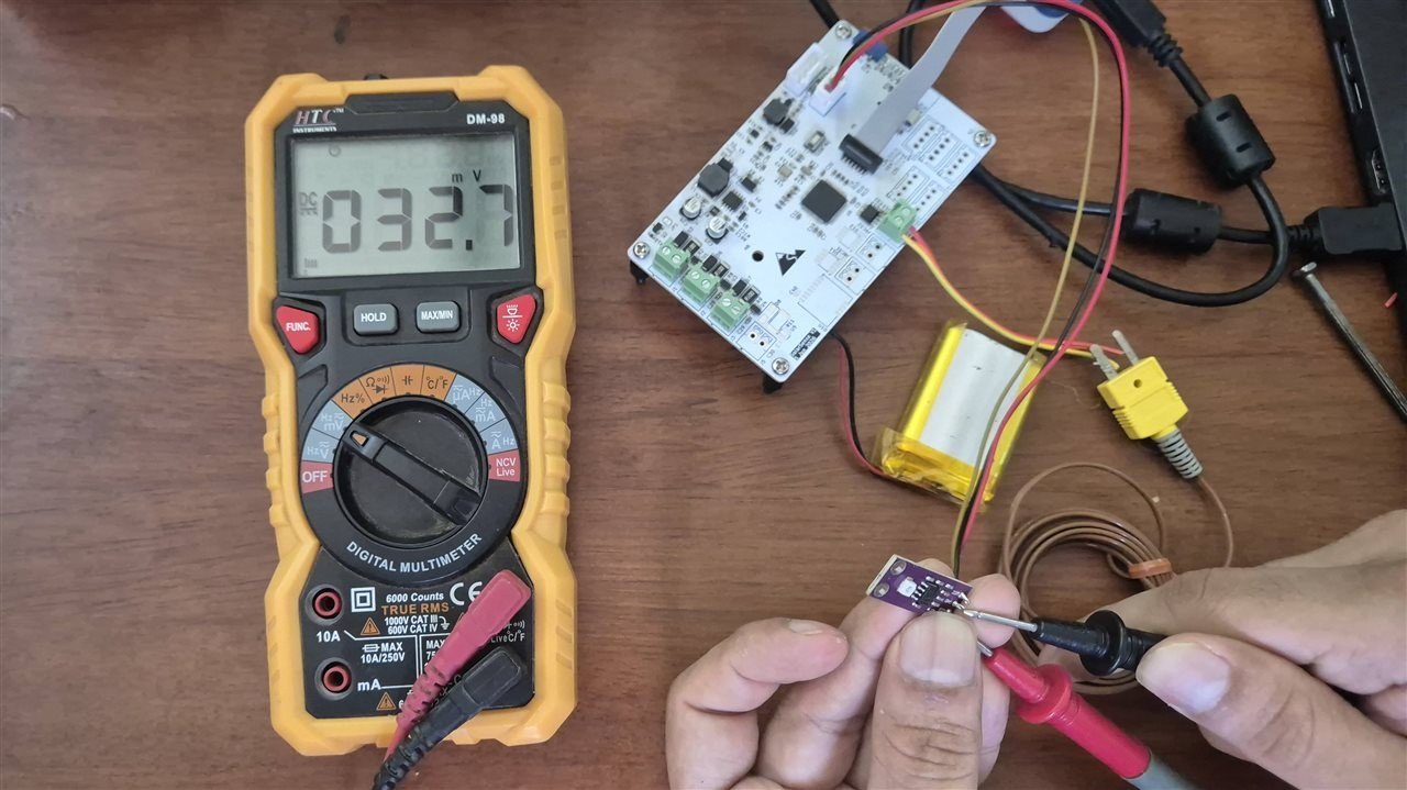
Why a third humidity and temperature sensor? The SEN66 and BMP280 sit inside the enclosure, where the board and the SEN66’s fan warm the air. The HX94C is an industrial probe on a cable, out in the real outdoor air. It sends its readings as a 4–20 mA current, so a long cable doesn’t change the reading the way it would for a voltage output.
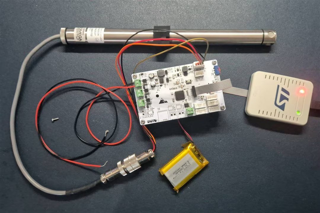
Why the SEN66 air-quality sensor? It measures dust in the air — the same dust that ends up on the panel.
A7. The Hardware — PCB
This board lives outdoors in Kerala: dry spells, 100% humidity, heavy monsoon rain, and air temperatures up to 50 °C — which can mean 60 °C inside a box. That is too harsh for a breadboard, so I designed a proper PCB from the start.
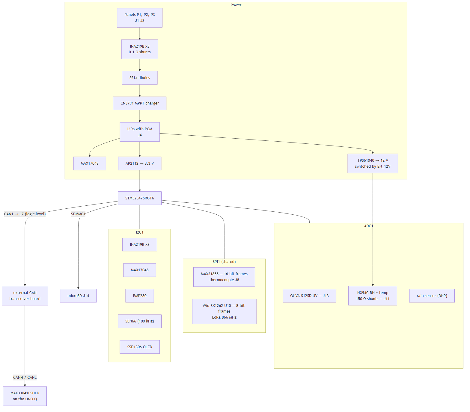
The schematic has five sheets, and each sheet is divided into labelled blocks. Fig 9 shows the overall picture: how power flows, and which bus each part sits on. Sections A7.1–A7.5 then explain each block with its piece of the schematic. The full sheets are in the Schematics section at the end.
A7.1 Sheet 1 — Solar input and panel measurement
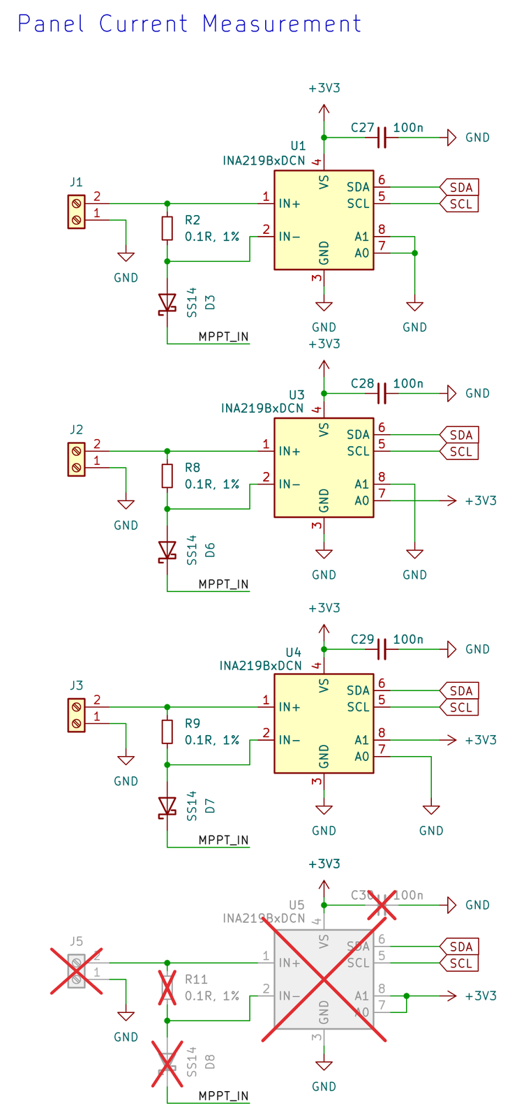
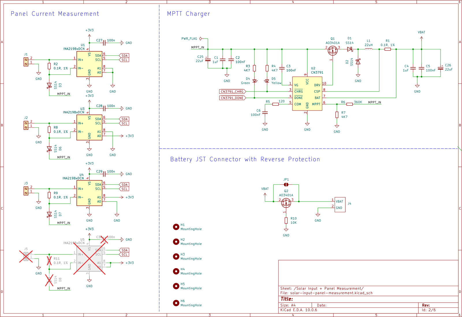
Panel current measurement. Each panel connects to its own screw terminal (J1, J2, J3; pin 1 is ground, pin 2 is positive). The panel’s current flows through a 0.1 Ω resistor (R2, R8, R9). An INA219B (U1, U3, U4) measures the small voltage across that resistor, which gives the current. The current then passes through an SS14 diode (D3, D6, D7) into the charger’s shared input, MPPT_IN.
The diodes let the three panels share one charger safely: a clean panel at a higher voltage can’t push current backwards into a dirty one. Each INA219B sits before its diode, so it measures only its own panel. The address pins (A0/A1) give each chip a different I²C address: 0x40, 0x41 and 0x44. A fourth channel (U5, R11, D8, J5) is drawn but not fitted — it’s crossed out on the sheet, a spare for a fourth panel.
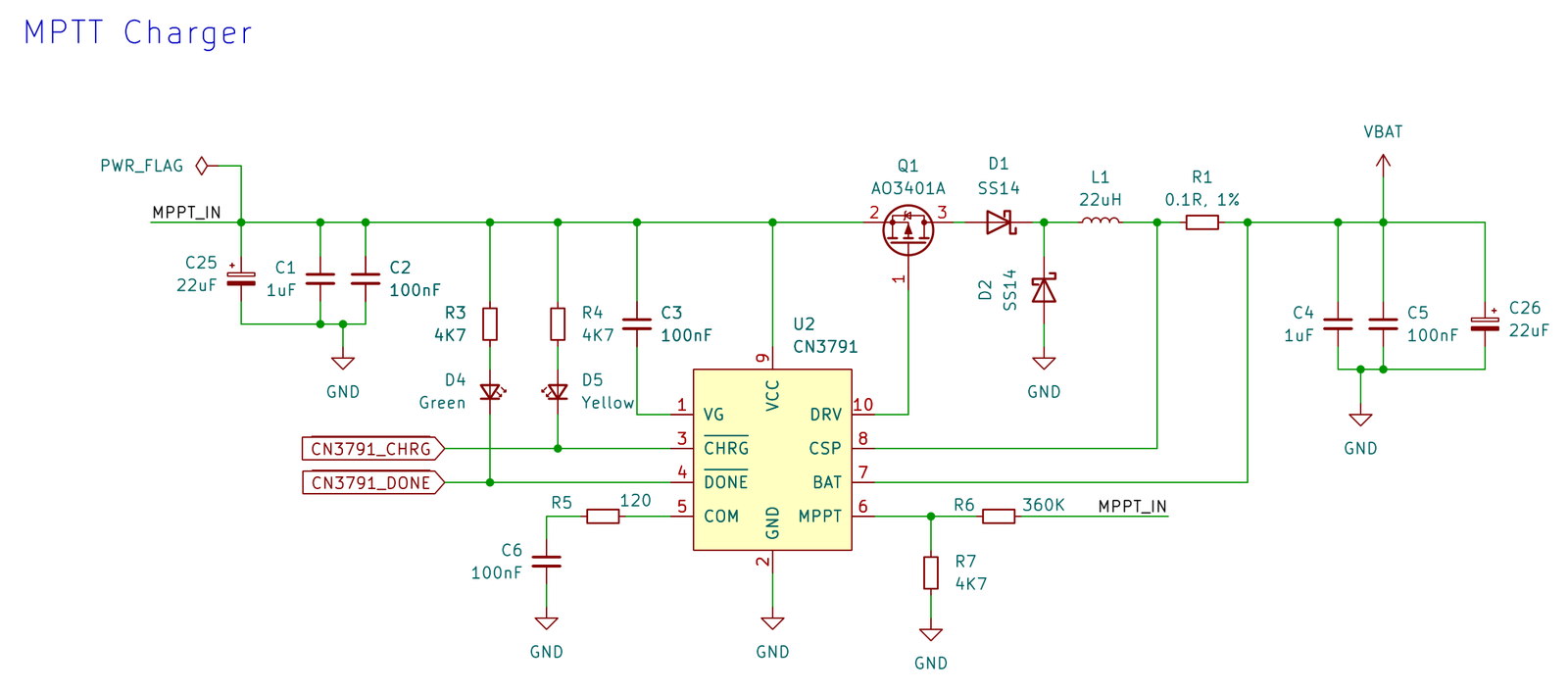
MPPT charger. The CN3791 (U2) charges the LiPo battery from the panels, while keeping the panels at the voltage where they give the most power. It is a step-down (buck) converter: it switches the P-MOSFET Q1 (AO3401A), which feeds the 22 µH inductor L1 through D1. D2 carries the inductor current while Q1 is off.
- Charge current: R1 (0.1 Ω) measures the charge current and limits it to about 1.2 A. Below that limit, the charge current simply follows how much power the panels give.
- Panel voltage: the divider R6/R7 on
MPPT_INsets the voltage the charger holds the panels at. With 360 kΩ and 100 kΩ against the chip’s 1.205 V reference, that is 5.54 V — the panels’ best operating point is 5.5 V. The bench test measured 5.54 V. - Status: the CHRG and DONE pins light a yellow (D5) and a green (D4) LED, through 4.7 kΩ resistors. They also go to the STM32 (PB14/PB15), so the firmware knows when the battery is charging or full. Stability: R5 and C6 keep the charger’s control loop stable.
This is also the charger behind the battery over-voltage problem in B6.
BOM correction: the schematic and BOM still list R7 as 4K7. With 4.7 kΩ the panel-voltage setpoint would be about 93 V — far above what a 5.5 V panel can give. Fit 100 kΩ.
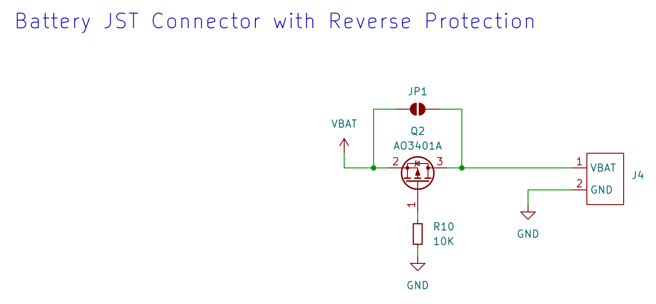
Battery connector and reverse protection. The LiPo plugs into J4 (2-pin JST PH). Q2 (another AO3401A) protects against plugging the battery in backwards; its gate is tied to ground through R10 (10 kΩ). With the battery the right way round, the MOSFET turns fully on and almost no voltage is lost. Plugged in backwards, it stays off and no current flows. JP1 is a solder jumper that can bypass Q2; it is open by default. In B6 I suspect this circuit of upsetting the charger’s voltage sensing.
A7.2 Sheet 2 — STM32L476RGT6
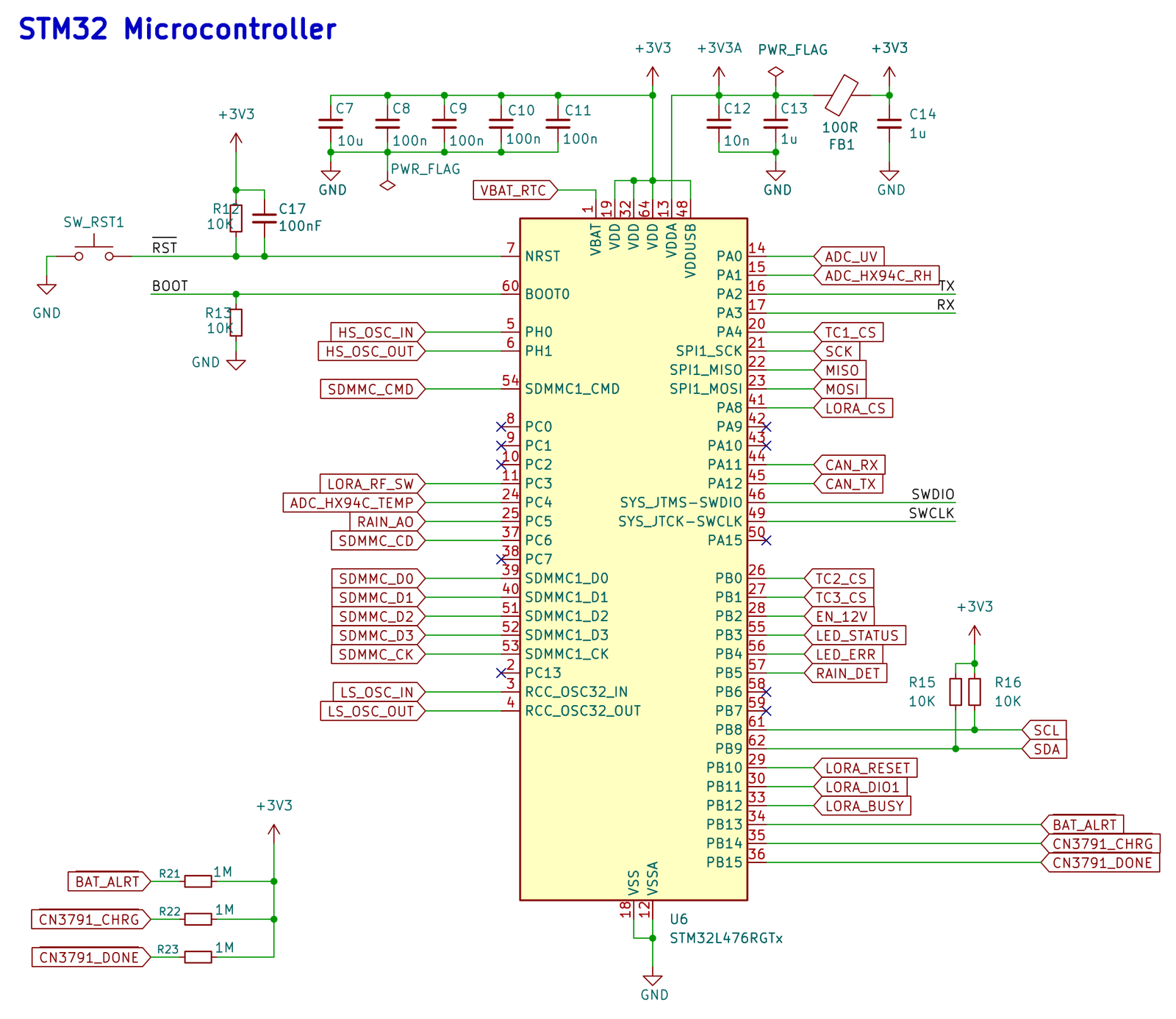
Microcontroller. I chose the STM32L476 mainly because I had several on hand and it has a built-in CAN controller.
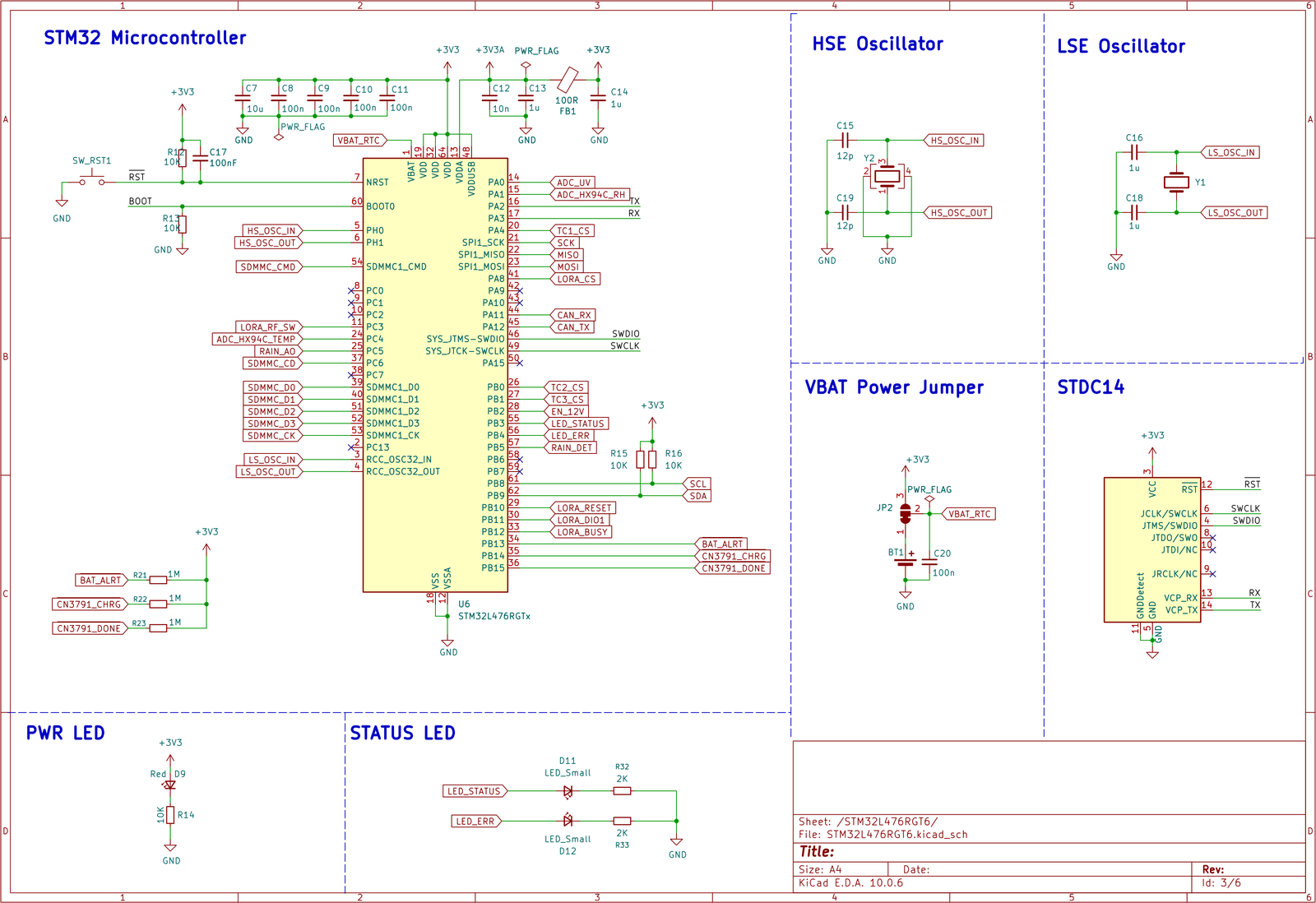
- Power: 10 µF, plus 100 nF on each supply pin. The ADC’s analog supply (VDDA) — which the UV and HX94C readings depend on — is filtered through a 100 Ω ferrite bead (FB1), with its own 10 nF and 1 µF. Reset and boot: a 10 kΩ pull-up, 100 nF and the SW_RST1 button for reset. BOOT0 is pulled low (R13), so it always starts from its own flash memory.
- Pull-ups: R15/R16 (10 kΩ) for the I²C bus. The three status lines from the charger and fuel gauge (
BAT_ALRT,CN3791_CHRG,CN3791_DONE) use 1 MΩ pull-ups (R21–R23), to waste as little current as possible.
The full pin list is the table in A11.
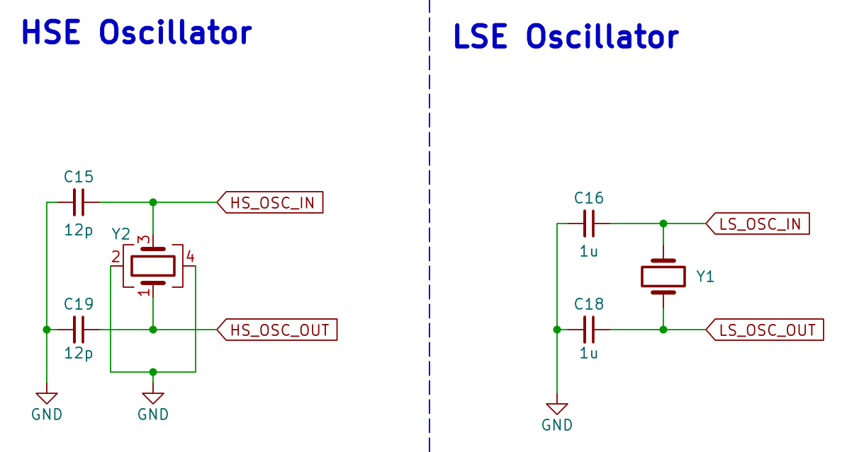
Clocks. Y2 is the 16 MHz main crystal, with 12 pF capacitors (C15, C19). Y1 is a 32.768 kHz crystal for the real-time clock (RTC), which keeps time and wakes the board from sleep. The schematic shows C16 and C18 as 1 µF. That was an oversight on my part — the fitted parts are 12 pF, which is what this crystal needs.
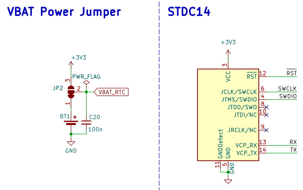
Clock backup supply and programming connector. The STM32 has a small backup section that keeps the RTC and a few memory registers alive. The 3-way solder jumper JP2 chooses what powers it: the CR2032 coin cell BT1 (the default) or the 3.3 V rail. With the coin cell, the clock and the saved LoRa settings (A10.4) survive even when the LiPo is flat. J6 is ST’s 14-pin STDC14 connector for an ST-Link programmer. It carries the programming lines (SWD), reset, and the board’s serial console (USART2).
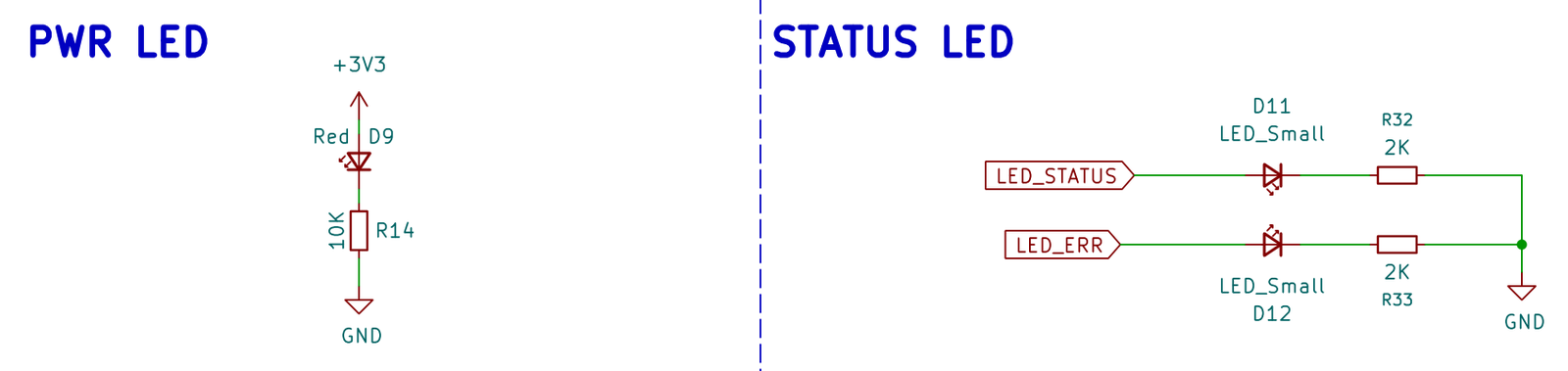
LEDs. A red power LED (D9, 10 kΩ), and two LEDs the firmware controls through 2 kΩ resistors: status (D11, PB3) and error (D12, PB4). For example, the error LED lights when a microSD card is inserted but won’t start up.
A7.3 Sheet 3 — Power management
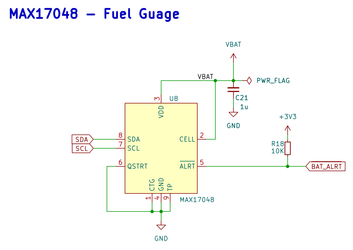
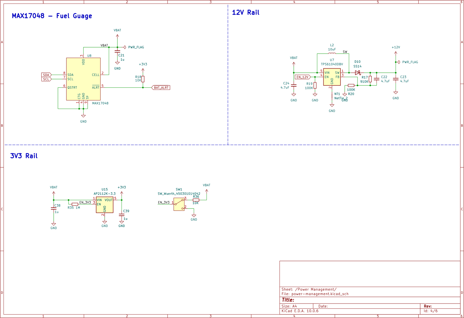
Fuel gauge. The MAX17048 (U8, I²C address 0x36) measures the LiPo voltage directly and works out the battery’s state of charge from it — no sense resistor needed. It is powered from the battery ( VBAT, with C21, 1 µF). When something needs attention, its alert output pulls BAT_ALRT (PB13, 10 kΩ pull-up R18) low, and the firmware logs it.
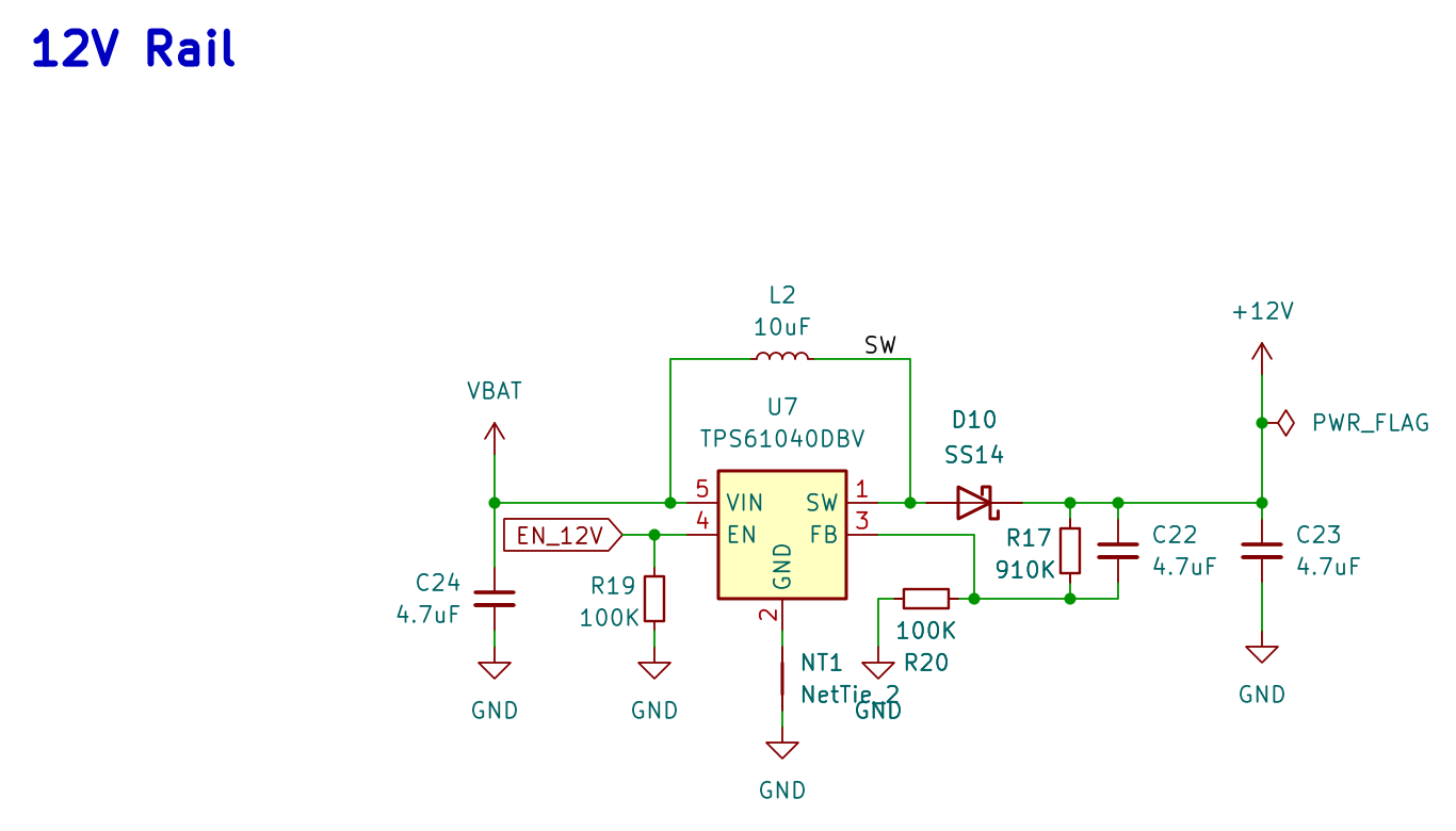
12 V supply. The HX94C probe needs 6–30 V to run. A TPS61040 (U7) boost converter raises the LiPo voltage to 12 V, using the 10 µH inductor L2 and the SS14 diode D10. The divider R17/R20 (910 kΩ / 100 kΩ) sets the output: 1.233 V × (1 + 910/100) ≈ 12.4 V.
The boost is switched by PB2 ( EN_12V). A 100 kΩ pull-down (R19) keeps it off at power-up. The firmware turns it on only when the HX94C is in use, and switching the HX94C off from the base station (A10.4) cuts this supply completely.
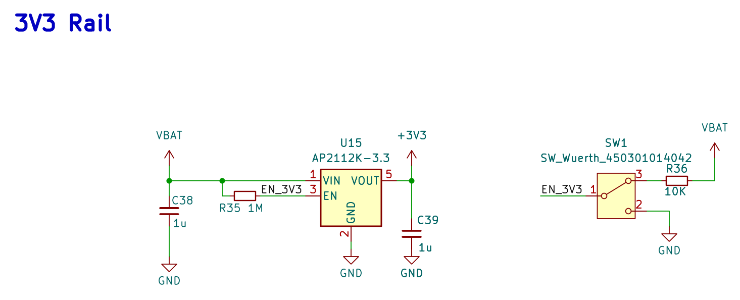
3.3 V supply. An AP2112K-3.3 regulator (U15) makes 3.3 V straight from the LiPo, with 1 µF on its input and output, and powers everything else. R35 (1 MΩ) keeps it switched on by default. The slide switch SW1 connects its enable pin either to the battery (through R36, 10 kΩ) or to ground — this switch is the board’s main on/off.
A7.4 Sheet 4 — Communications
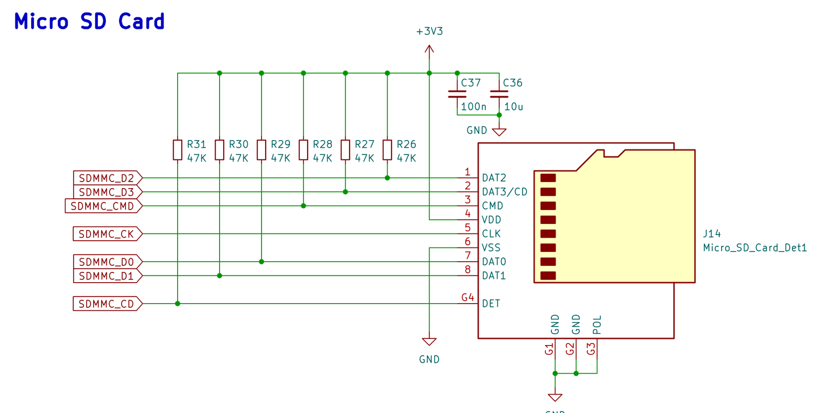
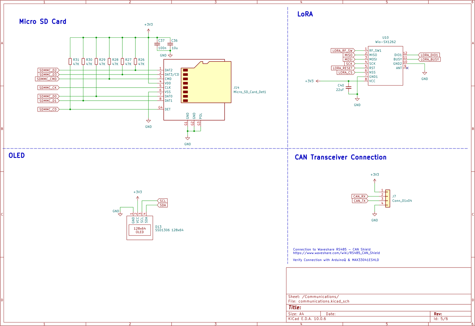
MicroSD card. J14 connects to the STM32’s 4-bit SD-card interface (SDMMC: data lines D0–D3, command and clock). 47 kΩ pull-ups sit on the data, command and card-detect lines, with 10 µF + 100 nF on its supply. The card keeps a local backup log for when the CAN cable isn’t connected.
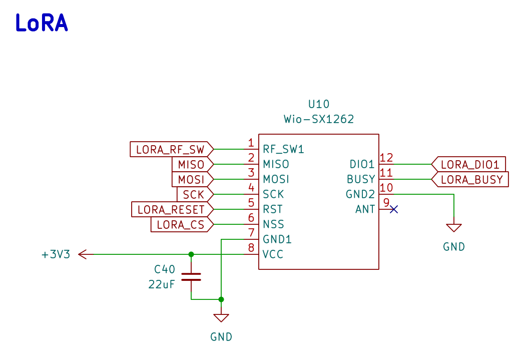
LoRa. U10 is Seeed’s Wio-SX1262 LoRa module. It shares the SPI1 bus with the thermocouple amplifier, and has its own chip select ( LORA_CS), reset, BUSY and DIO1 lines. LORA_RF_SW (PC3) controls its antenna switch. C40 (22 µF) supplies the short bursts of current when it transmits. The module’s ANT pin (9) isn’t used on the PCB.
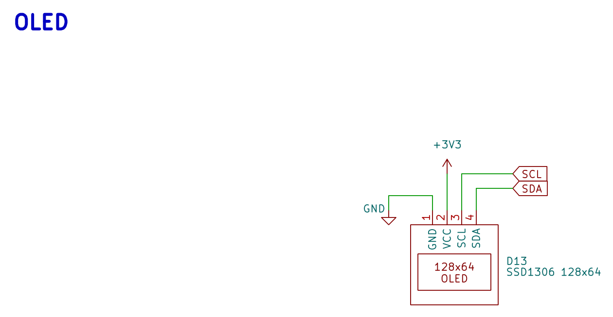
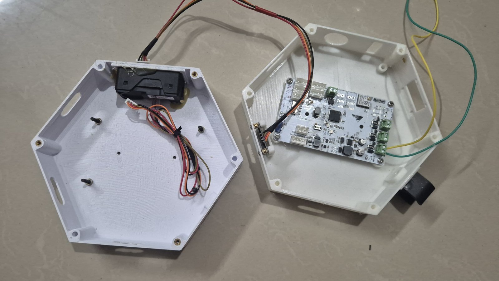
OLED. D13 is a 4-pin connector for a 128×64 SSD1306 OLED display on I²C (address 0x3C). It started as a debug display. It is now permanently fitted in the second node enclosure (A8, Fig 31), where it also acts as a load that stops the battery sitting at full (B7).
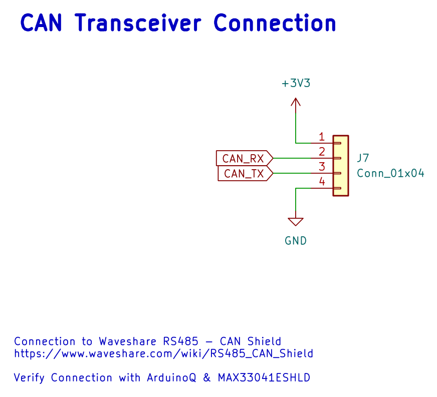
CAN connection. This board has no CAN transceiver chip. J7 brings out the STM32’s CAN transmit and receive lines at logic level, plus 3.3 V and ground: pin 1 = 3.3 V, pin 2 = CAN_RX, pin 3 = CAN_TX, pin 4 = GND. They go to a Waveshare RS485/CAN board (as the note on the sheet says), which converts them into the CANH/CANL signals that travel on the cable. See A11.
A7.5 Sheet 5 — Sensors
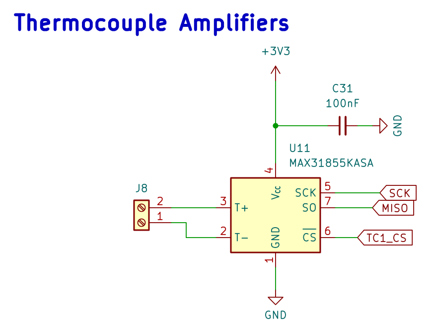
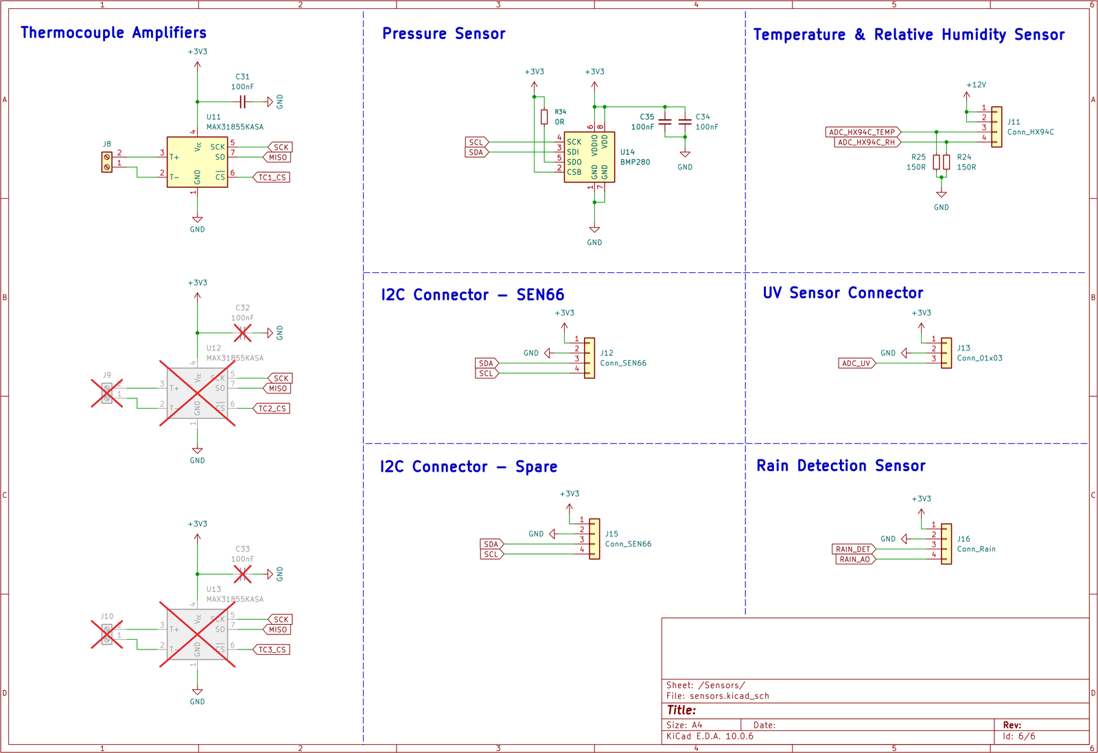
Thermocouple amplifier. U11 (MAX31855KASA) reads the K-type thermocouple on screw terminal J8 (T+, T−). It corrects for the temperature of its own connection point (cold-junction compensation) and sends the result to the STM32 over SPI1. It has 100 nF on its supply. Two more identical channels (U12, U13, with J9 and J10) are drawn but not fitted — they’re crossed out on the sheet, ready for thermocouples on the other two panels.
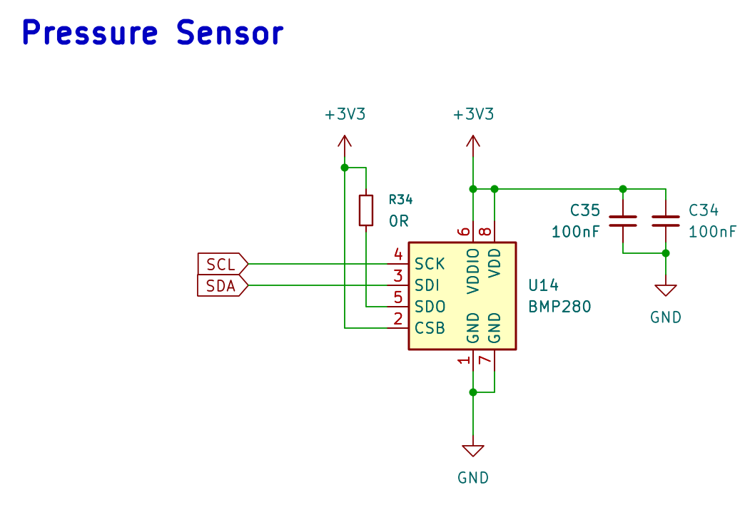
Pressure sensor. The BMP280 (U14) is set up for I²C: CSB is tied high, and SDO is pulled high through R34 (0 Ω). That gives it address 0x77. (The driver tries 0x76 first, then 0x77, so it finds it either way.) Two 100 nF capacitors decouple its supplies.
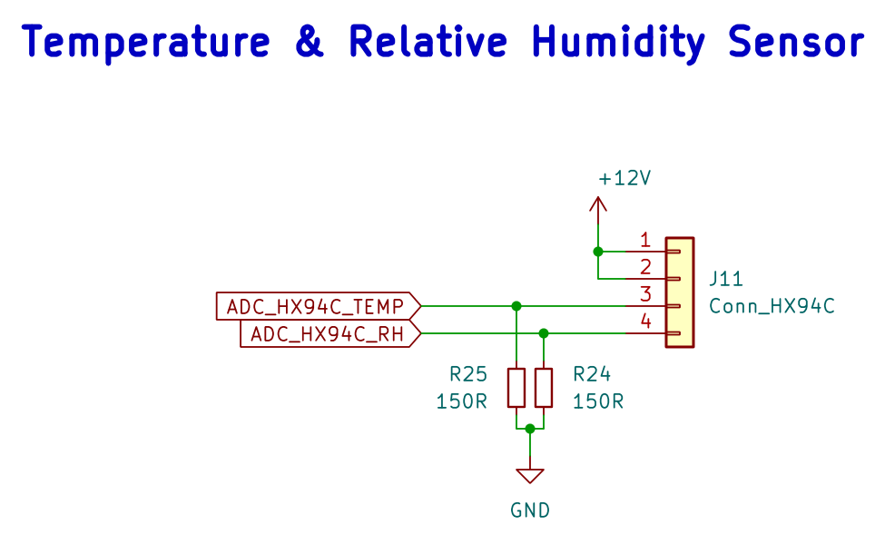
HX94C temperature and humidity. J11 gives the probe 12 V on pins 1–2, from the switchable supply in A7.3. Pins 3 and 4 carry its two outputs — temperature and humidity — each as a 4–20 mA current. Each returns to ground through a 150 Ω resistor (R25, R24), which turns 4–20 mA into 0.60–3.00 V. The STM32’s ADC reads those voltages directly (PC4 and PA1).
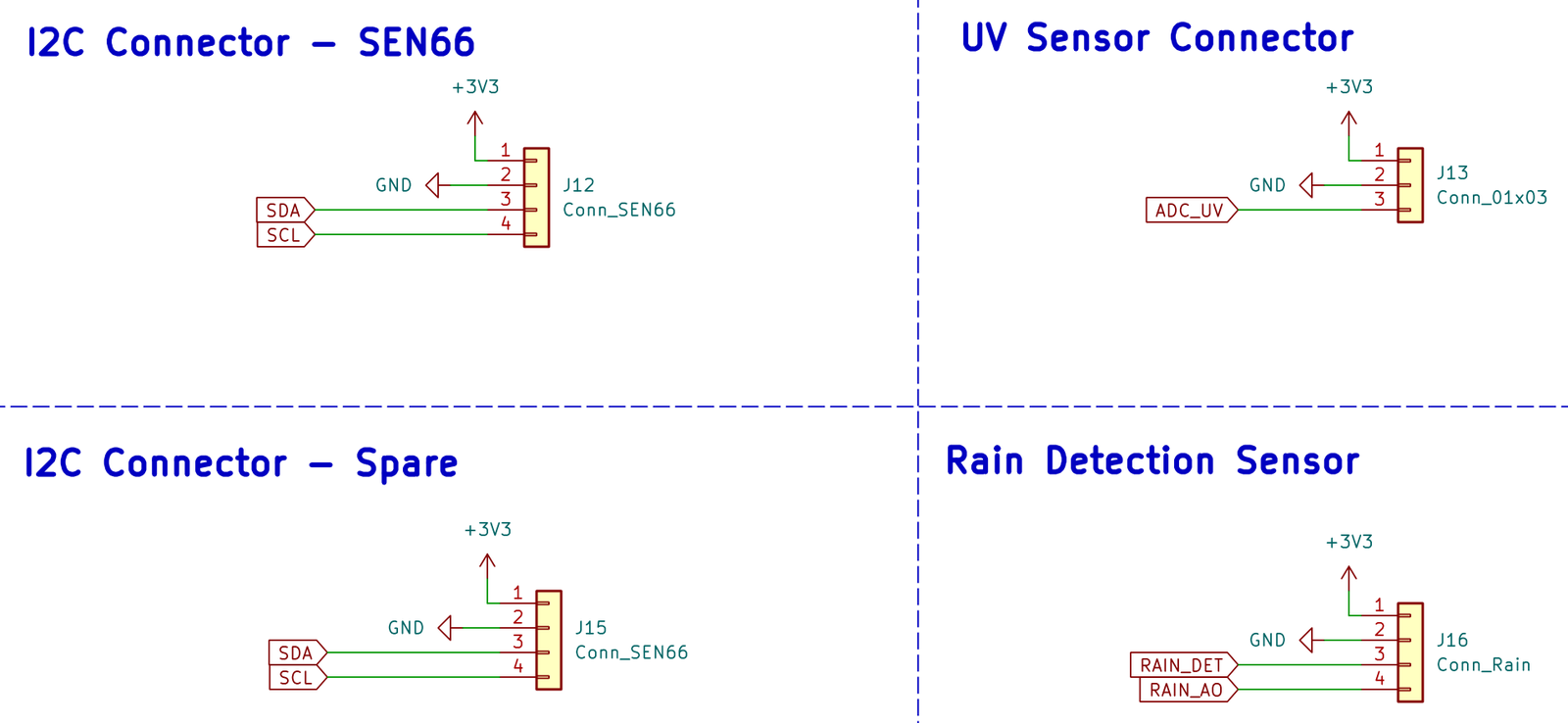
Sensor connectors. J12 is for the SEN66 (3.3 V, GND, SDA, SCL), and J15 is a spare with the same I²C pinout. J13 is for the GUVA-S12SD UV sensor (3.3 V, GND, analog output to PA0). J16 is for a rain sensor (3.3 V, GND, a digital detect line on PB5 and an analog line on PC5) — routed, but nothing plugged in yet.
I had the PCB made by PCB Way with white solder mask — white absorbs less heat in direct sun. The enclosure is white for the same reason.
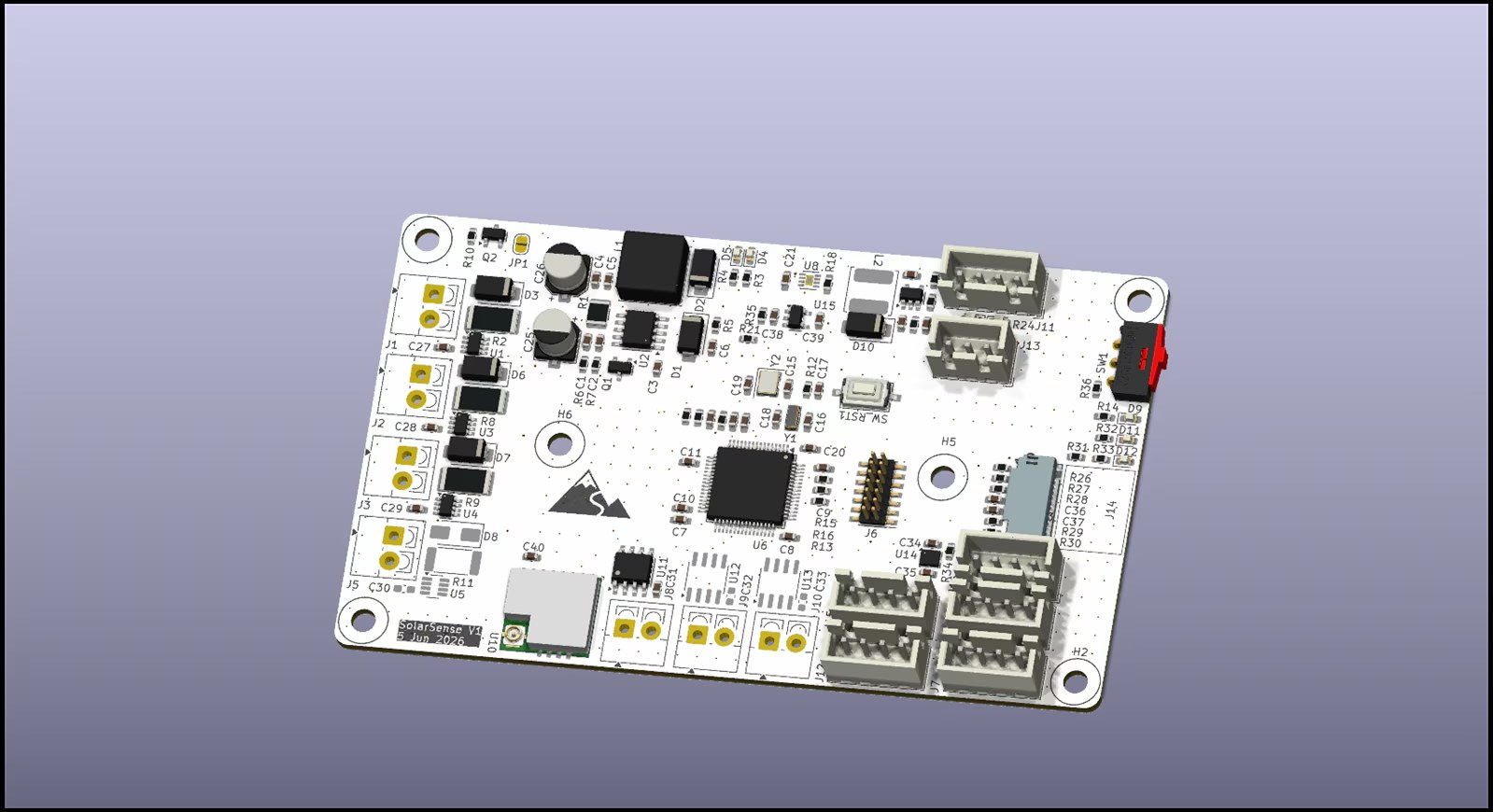
A8. Mechanical Build
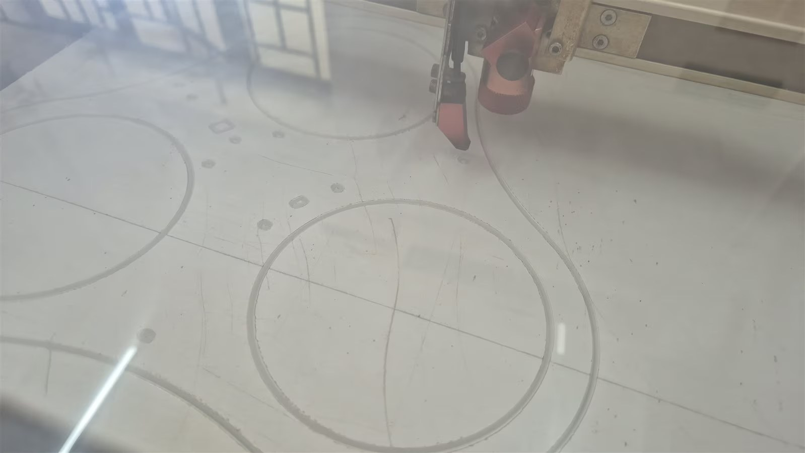
I laser-cut a white acrylic plate that holds the three panels in a triangle, with holes for the rain and UV sensor connectors, and a matching box for the electronics. I didn’t have PETG, so the box is printed in PLA for now. A scaling mistake when laser-cutting meant I had to 3D print a spacer to get a snug fit. The wall clip that comes with the HX94C turned out to be a handy way to mount it on the side of the box.
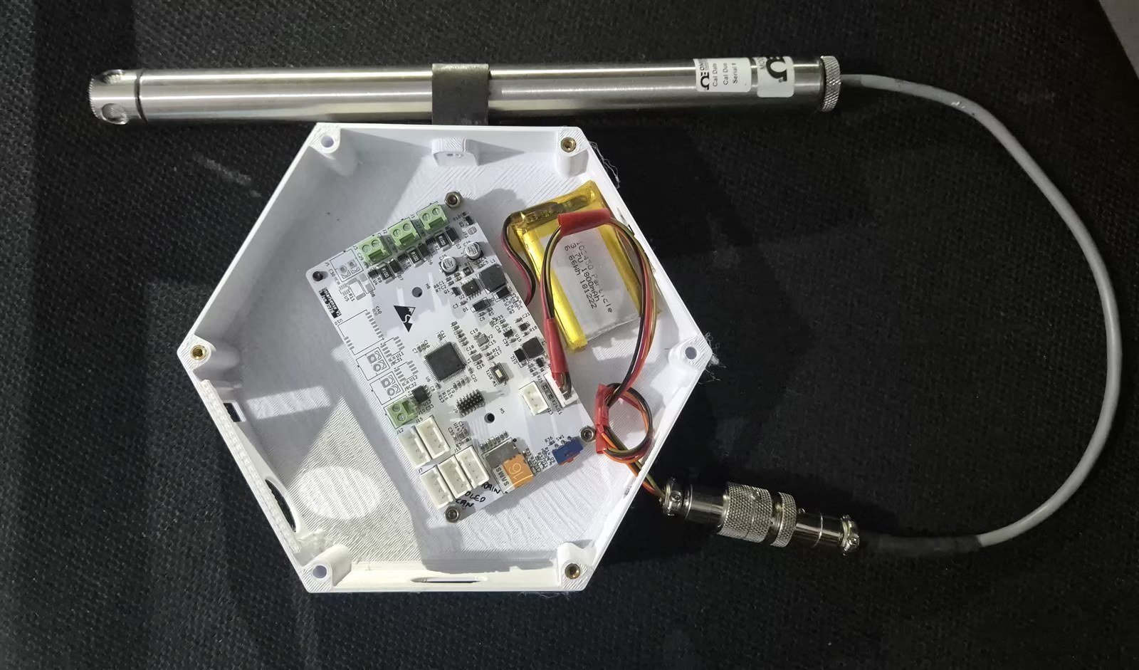
I later made a second version of the node enclosure with the OLED permanently fitted. The OLED started as a debug display and ended up doing a more useful job as a load (B7).
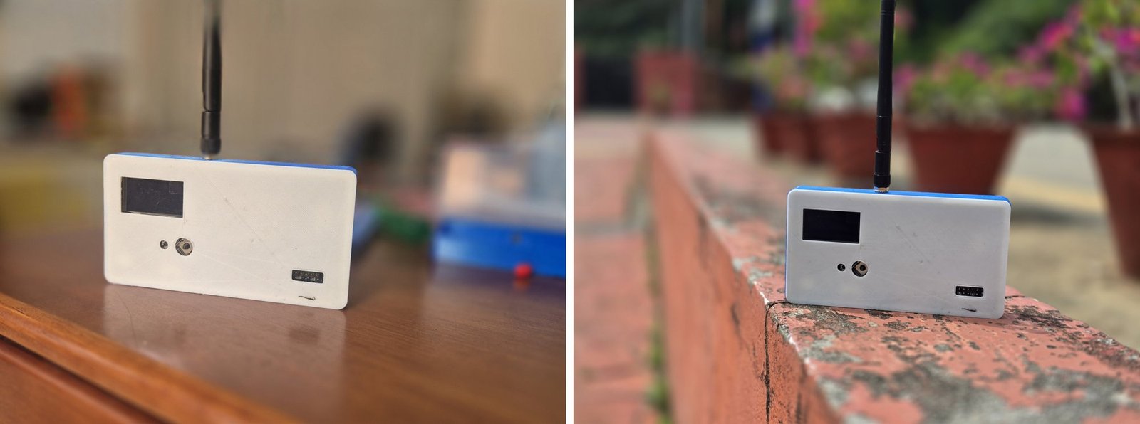
For the final deployment and testing, I 3D printed a case for the indoor side: the Arduino UNO Q and the Wio Tracker L1 together. That turns the gateway into one tidy unit instead of two loose boards and a set of jumper wires.
A9. Code Structure
All the code is in the solar-sense/ folder of the shared Drive folder. These are the parts that matter, with what each one does:
solar-sense/
├── solar-sense-v1-fw/            STM32L476 node firmware (make + arm-none-eabi-gcc)
│   ├── Core/Src/main.c           bring-up, 5 s sensor heartbeat, STOP2 sleep, console
│   ├── Core/Src/ina219.c         panel V / I / P (x3)
│   ├── Core/Src/max31855.c       thermocouple, SPI1 in 16-bit frames
│   ├── Core/Src/hx94c.c          4-20 mA RH + temp through the 150 Ω shunts
│   ├── Core/Src/sen66.c          air quality, I2C @ 100 kHz
│   ├── Core/Src/bmp280.c         pressure + board temp
│   ├── Core/Src/max17048.c       battery fuel gauge
│   ├── Core/Src/ssd1306.c        debug OLED
│   ├── Core/Src/can_tlm.c        packs everything into 10 CAN frames (0x100–0x109)
│   ├── Core/Src/sx1262.c         bare-metal SX1262 driver (no RadioLib), shares SPI1
│   ├── Core/Src/lora_node.c      wake → sample → TX → RX window → sleep state machine
│   └── pa6-test/                 standalone pin-blink harness, used to find the cold joints
│
├── lora-link/                    LoRa wire format — portable C99, compiled by BOTH ends
│   ├── lora_link.h / .c          frames, CRC16, TLM/CONFIG_SET/CMD codecs, lora_airtime_ms()
│   └── test/test_lora_link.c     host test suite (make test)
│
├── wio-base/                     Wio Tracker L1 base firmware (PlatformIO + RadioLib)
│   └── src/
│       ├── main.cpp              RX loop, reconciliation reply, LTLM line for the UNO Q
│       ├── console.cpp           set / dump / cmd / stay-awake … and the `ai` command
│       ├── display.cpp           OLED: link page + SOILING page
│       ├── base_state.h          desired config, per-node table, AI verdict
│       └── config_store.cpp      desired config persisted to flash
│
├── nucleo-code/qstm-can-receiver/  UNO Q STM32U585 bare-metal firmware (FDCAN + LPUART)
├── arduinoq-bridge/              CAN frame reassembly → one TLM text line (recv_mask)
│
├── host-software/
│   ├── bridge/serial_bridge.py   UNO Q Linux: CAN TLM → ratios → Edge Impulse ingestion
│   └── lora-ai/
│       ├── lora_ai_bridge.py     UNO Q Linux: LTLM → .eim → `ai` verdict back to the base
│       └── solarsense-lora-ai.service   systemd autostart
│
├── solar-sense-pcb/              KiCad project (5 sheets), BOM
├── CAN_PROTOCOL.md               CAN frame layout
└── LORA_PROTOCOL.md              LoRa protocol spec — every function cites a § in here
And which chip each piece runs on:
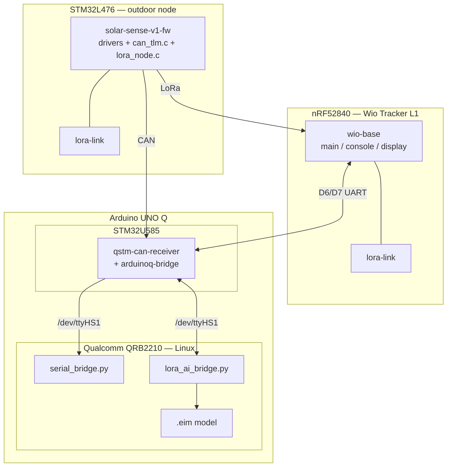
lora-link is the same code, built into both ends of the LoRa link.One rule I followed: anything that defines a message format is shared code, never copied. The CAN and LoRa message layouts are each defined once, and so is the LoRa airtime calculation. So when I found a bug in that calculation (B10), one fix in lora-link corrected both the node and the base.
A10. Coding Explanation and Configuration
This section follows one reading from the panel all the way to the OLED screen.
A10.1 The node’s main loop
The STM32L476 runs two loops: a 5-second heartbeat that reads every sensor and sends the CAN messages, and a LoRa exchange once per wake-up interval, after which it can sleep:
/* every 5 s (or on a "status" command): read sensors, fill the TLM struct */
if (force_report || (stream_enabled && (now - last_heartbeat >= 5000U)))
{
    ...                                   /* INA219 x3, MAX31855, HX94C, UV, SEN66 … */
    CAN_TLM_Send(&hcan1, &can_tlm);       /* 10 CAN frames */
}
/* LoRa Class-A exchange: paced internally by wake_interval_s */
lora_node_task(now, &g_last_tlm, g_have_tlm != 0);
/* then sleep in STOP2 until the next wake */
if (powersave && lora_node_ready() && !maint_mode && now >= BOOT_AWAKE_MS)
{
    uint32_t sleep_s = lora_node_presleep_s(now);
    if (sleep_s)
    {
        Power_EnterStop2(sleep_s);   /* returns after the full interval */
        lora_node_notify_wake();     /* next task() runs a fresh exchange */
    }
}
This gives the board two operating modes, switched from its serial console:
| Mode | Console command | What happens | Used for |
|---|---|---|---|
| Data collection | powersave off | stays awake and sends CAN every 5 s | collecting training data for Edge Impulse |
| Power save (default) | powersave on | wakes, sends one LoRa packet, then sleeps; CAN only sends during the short awake time | running on the battery, unattended |
After a reset, the board always stays awake for 15 seconds, so there’s time to type a console command before it starts sleeping.
All values are sent as whole numbers, not decimals: millivolts, tenths of a milliamp, hundredths of a °C, tenths of a percent humidity. The receiving end converts them back. (The microcontroller’s print function has no decimal support, and whole numbers are smaller and exact.)
A10.2 Reading the sensors
Panel current and power (INA219B). The driver reads the voltage across the shunt resistor and calculates the current itself with Ohm’s law, instead of relying on the chip’s built-in calibration:
/* I(uA) = Vshunt(uV) / R(Ohm) = Vshunt(uV) * 1000 / R(mOhm). */
*ua = (uv * 1000) / INA219_RSHUNT_MOHM;
...
/* P(mW) = V(mV) * I(mA) / 1000 */
*mw = (int32_t)(((int64_t)bus_mv * ua) / 1000000);
Panel surface temperature (MAX31855). This chip has no settings to configure. The STM32 pulls chip-select low and reads 32 bits. SPI1 is shared with the LoRa radio and set to 16-bit transfers for this chip, so the 32 bits are read as two 16-bit transfers:
static HAL_StatusTypeDef read_raw(MAX31855_t *dev, uint32_t *raw) {
    uint16_t w[2];
    HAL_GPIO_WritePin(dev->cs_port, dev->cs_pin, GPIO_PIN_RESET);
    HAL_StatusTypeDef st = HAL_SPI_Receive(dev->hspi, (uint8_t *)w, 2, SPI_TIMEOUT_MS);
    HAL_GPIO_WritePin(dev->cs_port, dev->cs_pin, GPIO_PIN_SET);
    if (st == HAL_OK) *raw = ((uint32_t)w[0] << 16) | w[1];
    return st;
}
The thermocouple temperature is in bits 31–18 (0.25 °C per step), the chip’s own temperature in bits 15–4 (0.0625 °C per step), and bits 2–0 flag a broken or shorted probe.
Outdoor humidity and temperature (HX94C). Each 4–20 mA output flows through a 150 Ω resistor, giving 0.60–3.00 V at the ADC. The code converts voltage → current → reading, along a straight line from 4 mA to 20 mA:
int32_t i_rh = (int32_t)(rh_mv * 1000U / HX94C_RSENSE_OHMS);   /* µA */
if (i_rh < HX94C_LOOP_LO_UA)      f |= HX94C_FLT_RH_OPEN;       /* broken wire */
else if (i_rh > HX94C_LOOP_HI_UA) f |= HX94C_FLT_RH_OVER;
/* in map_loop(i_ua, lo, hi): 4-20 mA onto the sensor's range */
return lo + (int32_t)(((int64_t)(i_ua - 4000) * (hi - lo)) / 16000);
A current loop gives fault detection for free: below 4 mA means the wire is broken, which a voltage sensor can’t tell you. The ADC uses a long sampling time ( ADC_SAMPLETIME_640CYCLES_5) because the signal source has a high impedance.
UV (GUVA-S12SD). According to Adafruit, UV index = output voltage ÷ 0.1 V. The software on the UNO Q uses 110 mV per index instead ( UV_MV_PER_INDEX) — a starting value I still need to check outdoors against a reference meter. On the STM32L4, the ADC must be calibrated before use, or the readings are wrong:
HAL_ADCEx_Calibration_Start(&hadc1, ADC_SINGLE_ENDED); /* skip this and readings are wrong */A10.3 The CAN path — data collection
Standard CAN: 11-bit message IDs, 8 bytes of data per message, 500 kbit/s. Each snapshot is 10 messages:
| ID | Name | Contents |
|---|---|---|
| 0x100 | SYS | Battery mV, SOC, charger state, 12V rail flag, SD flag, UV mV |
| 0x101 | P1 | Panel 1: ok flag, bus mV, current (tenths mA), power mW |
| 0x102 | P2 | Panel 2: same |
| 0x103 | P3 | Panel 3 (clean reference): same |
| 0x104 | TC | Thermocouple: ok, fault, surface temp, cold-junction temp |
| 0x105 | BMP | BMP280: ok, board temp, pressure |
| 0x106 | HX | HX94C: ok, fault, RH, temp, loop current |
| 0x107 | AQ-PM | SEN66: PM1.0, PM2.5, PM4.0 |
| 0x108 | AQ-Gas1 | SEN66: PM10, internal RH, internal T, VOC index |
| 0x109 | AQ-Gas2 | SEN66: NOx index, CO2 ppm |
On the node, can_tlm.c packs each value into its message, low byte first:
/* 0x101–0x103 — solar panels */
for (int i = 0; i < 3; i++) {
    d[0] = t->p_ok[i];
    d[1] = 0U;
    PUT16(d, 2, (uint16_t)t->p_mv[i]);
    PUT16(d, 4, (uint16_t)t->p_ma[i]);   /* p_ma holds tenths of a mA despite the name */
    PUT16(d, 6, (uint16_t)t->p_mw[i]);
    send_frame(hcan, CAN_TLM_ID_P1 + (uint32_t)i, d);
}
send_frame() never waits. CAN is an extra path, and a disconnected cable must never stop the board from measuring:
if (HAL_CAN_GetError(hcan) & CAN_FAULT_MASK) return HAL_ERROR;   /* bus fault: bail */
if (HAL_CAN_GetTxMailboxesFreeLevel(hcan) == 0) return HAL_BUSY; /* no mailbox: drop */
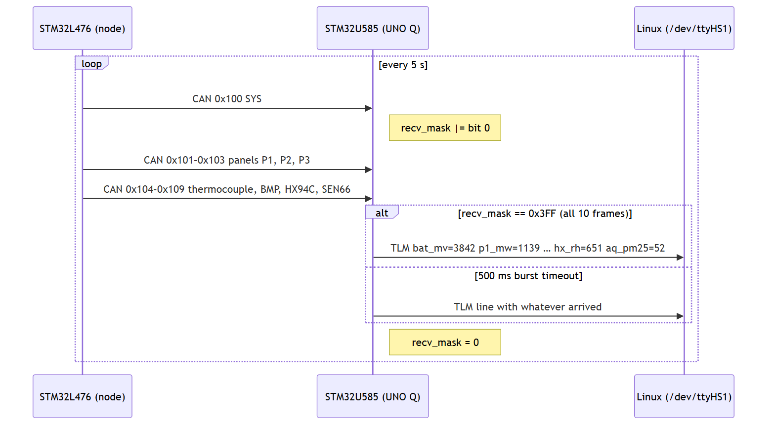
On the UNO Q, its STM32U585 collects the messages. Each one sets one bit in a 10-bit recv_mask. When all ten have arrived — or 500 ms passes with some missing — it turns them into one line of text for the Linux side:
if (s_recv_mask == FRAME_ALL_MASK ||
    (s_recv_mask != 0U &&
     (HAL_GetTick() - s_burst_start_ms) >= BURST_TIMEOUT_MS)) {
    emit_tlm();                 /* "TLM bat_mv=… p1_mw=… hx_rh=…" over LPUART */
    s_recv_mask      = 0U;
    s_burst_start_ms = 0U;
}
On the Linux side, serial_bridge.py reads that line from /dev/ttyHS1 (the serial port between the STM32 and Linux), calculates the ratios, and uploads 30-second batches to Edge Impulse. This was the first way data reached Edge Impulse; how it relates to the current model is in A10.3b:
panel1_ratio = p1_mw / p3_mw   # P3 is the clean reference
panel2_ratio = p2_mw / p3_mw
humidity     = hx_rh / 10.0    # tenths %RH
temp         = hx_t / 100.0    # centi-degC
uv_index     = uv_mv / UV_MV_PER_INDEX
Each 30-second batch is labelled automatically, based on the dirtier of the two panels, before it’s uploaded. Below 0.90 means “schedule a clean”; below 0.75 means “clean now”:
def compute_alert(p1_ratio, p2_ratio) -> str:
    worst = min(p1_ratio or 1.0, p2_ratio or 1.0)
    if worst < config.THRESHOLD_URGENT:     # 0.75
        return "urgent"
    if worst < config.THRESHOLD_SCHEDULE:   # 0.90
        return "schedule"
    return "clean"
The same script can also ask Edge Impulse’s cloud service to classify the data, if EI_CLASSIFY_URL is set. A10.6 explains why the LoRa path runs the model locally instead.
A10.3b Training the model in Edge Impulse
These automatic labels were a starting point: they got data into Edge Impulse with some label attached. They don’t match the models below one-to-one:
- The script: 6 inputs, every 5 s, labels
clean / schedule / urgent. - The current model (v2): 7 inputs, one sample per minute, labels
alert / clean / soiled.
So the v2 dataset was prepared separately from these automatic labels, as one-minute samples of the seven inputs in the table below. The two details of that preparation the LoRa AI bridge must match — how perf_ratio is computed, and the window length — are checked in B11.
The window length the current model expects is stored in the model file itself, and the LoRa AI bridge reads it from there (B11).
The first model was trained on about one day of field data. Its results (Fig 49):
| Predicted alert | Predicted clean | Predicted soiled | |
|---|---|---|---|
| Actual alert | 93.1% | 0% | 6.9% |
| Actual clean | 18.1% | 65.2% | 16.7% |
| Actual soiled | 46.8% | 4.9% | 48.3% |
Validation accuracy was 68.2%, with a loss of 0.70. The weak spot is the bottom row: almost half the soiled samples were called alert.
The current model (v2) is the public Edge Impulse project Solar sense, Impulse #1. This is the model exported as the .eim file for the UNO Q:
| Data | 223 h 28 min across 21 recordings (Edge Impulse calls each one a “sample”) |
|---|---|
| Inputs | 7 values — perf_ratio, i_control_a, i_test_a, uv_index, pm25, temp_c, rh_pct |
| Sample rate | one per minute (1/60 Hz) — the same rate as the LoRa packets |
| Processing | Flatten (summary statistics of each input over a time window) |
| Learning | Keras neural-network classifier, 3 classes: alert , clean , soiled |
| Validation accuracy | 99.8% |
| Edge Impulse’s estimate | about 1 ms per prediction, 15.4 KB, float32 (not optimised) — not yet measured on the UNO Q |
Going from 68.2% to 99.8% looks great, but I want to be careful with it. 223 hours is a lot of data, but it’s only 21 recordings. Edge Impulse cuts each recording into many short windows and then picks some of them for validation. So windows from the same recording — same day, same sky — can end up in both the training set and the validation set. There is also no separate test set yet. So 99.8% shows the model fits these 21 recordings very well. It doesn’t yet show it will be right on a day it has never seen. The real test is the LoRa AI bridge on new days (B11), with its log file to check each decision.
A10.4 The LoRa path — the node side
The node uses my own SX1262 radio driver ( sx1262.c) and a small step-by-step program ( lora_node.c): wake → measure → send → listen briefly → sleep. These are the radio settings, for India’s licence-free 865–867 MHz band:
| Parameter | Value |
|---|---|
| Frequency | 866.0 MHz |
| Bandwidth | 125 kHz |
| Spreading factor | SF9 (default at start-up; SF7 set from the base for bench tests) |
| Coding rate | 4/5 |
| Sync word | 0x12 (private network, not LoRaWAN) |
| Transmit power | 14 dBm (default) |
The LoRa packet (TLM) carries the same whole-number values as the CAN messages, but only for sensors that are fitted and switched on. The panel readings are the important part:
o->included_mask  = (uint16_t)(s_cap16 & (uint16_t)s_cfg.sensor_enable_mask
                                      & (uint16_t)s_cfg.tlm_group_mask);
...
for (int i = 0; i < 3; i++) {
    o->s.p_v_mv[i]  = t->p_mv[i];
    o->s.p_i_dma[i] = t->p_ma[i];
    o->s.p_p_mw[i]  = t->p_mw[i];
}
A packet with every sensor is 72 bytes, and takes 0.431 s to send at SF9. At one packet a minute, the radio is transmitting less than 1% of the time.
Settings: the base keeps the “desired” configuration. The node sleeps most of the time and can only hear the base for a moment after each packet it sends. So instead of sending commands, the base stores the settings it wants the node to have, with a version number and a checksum (CRC). Every packet from the node reports which settings it is actually using. If they don’t match, the base sends the full settings in that short listening window. However many changes I make while the node sleeps, they all arrive in one go.
From the base I can change how often the node wakes, the spreading factor and the transmit power — or switch a sensor off. Switching the HX94C off ( set sensors 0x1DF) also cuts its 12 V supply, so it is really off, not just ignored.
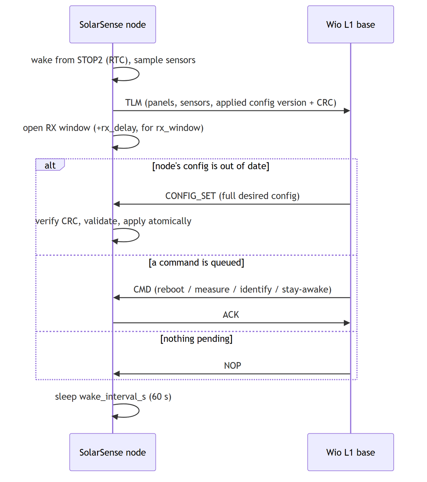
The listening window opens a little early and stays open a little late, so the base’s reply always arrives inside it:
#define RX_WINDOW_GUARD_MS 200u
uint32_t pre = (s_cfg.rx_delay_ms > RX_WINDOW_GUARD_MS)
                   ? (s_cfg.rx_delay_ms - RX_WINDOW_GUARD_MS) : 0u;
HAL_Delay(pre);                 /* open early: base TX is bracketed by GUARD */
uint32_t remaining = s_cfg.rx_window_ms + 2u * RX_WINDOW_GUARD_MS;
Sleep. Between wake-ups the node sleeps in STOP2 mode, and the real-time clock wakes it. The watchdog timer (about 26 s) keeps counting during sleep, so one long 60 s sleep would reset the board. The sleep is therefore split into chunks of 20 s or less, with a watchdog refresh in between. The current settings are copied into the clock’s backup registers, so they survive a reset. On every start-up the radio settings go back to safe defaults, so the node can always be reached.
Timeouts are calculated from the airtime, not guessed:
static uint32_t tx_timeout_ms(uint16_t frame_len)
{
    uint32_t toa = lora_airtime_ms(s_cfg.lora_sf, LORA_SAFE_BW_KHZ, LORA_SAFE_CR,
                                   frame_len);
    uint32_t budget = toa + toa / 2 + 200;   /* 1.5x airtime + fixed margin */
    return budget < 500u ? 500u : budget;
}
lora_airtime_ms() is in the shared lora-link library. It uses Semtech’s time-on-air formula, with whole-number maths only:
int cr_mult = (cr >= 5u && cr <= 8u) ? (int)cr : 5;   /* 4/5 → 5 */
int num = 8 * (int)frame_len - 4 * (int)sf + 28 + 16 * crc - 20 * ih;
int den = 4 * ((int)sf - 2 * de);
int ceilv = (num > 0) ? (num + den - 1) / den : 0;
int payload_symb = 8 + ceilv * cr_mult;
A10.5 The LoRa path — the Wio Tracker L1 base
The indoor end of the LoRa link is a Seeed Wio Tracker L1: an nRF52840 microcontroller, an SX1262 radio, a small OLED screen and a GPS module. It comes with Meshtastic firmware; I replaced that with my own (PlatformIO + RadioLib, in wio-base/).
In the final build the L1 sits in the same 3D-printed case as the UNO Q (Fig 32, A8), with its OLED showing through a window.
The base station:
- receives the node’s packets, decodes them and prints them on its serial console; stores the desired settings in flash, so a power cut doesn’t quietly reset the node to defaults; replies inside the node’s listening window (new settings, a command, or “nothing to do”); prints one
LTLMline per packet — a single line of text the UNO Q can read — on both its USB console and a second serial port (Serial1, pinsD6/D7); receives theairesult back from the UNO Q over that same serial port and shows it on the OLED (written and compiled, but not yet flashed to the board — B11).
The second serial port is needed because the UNO Q’s only USB-C port must stay free for power — see A10.6.
If a node reports that a sensor isn’t fitted, the base removes that sensor from the settings before sending them. Otherwise the node would (correctly) reject the settings:
LoRaConfig_t cfg = g_state.desired;
cfg.sensor_enable_mask &= n->capability;
cfg.tlm_group_mask     &= n->capability;
cfg.tlm_group_mask     &= cfg.sensor_enable_mask;   /* tlm ⊆ enable */
The LTLM line is printed after the reply to the node, never before. The node’s listening window is time-critical; the text line is not:
if (opens_window) reconcile_and_reply(n);
/* After the reply, not before: the node's RX window is timing-critical and
 * the gateway line is not. */
if (have_tlm) emit_ltlm(f->src, &tlm, rssi, snr);
The line holds the raw whole-number values, exactly as received, and only for sensors that reported. A missing value means “not reporting”, never zero:
LTLM src=1 rssi=-41 snr=10 mask=0x07F ... p1_dma=1834 p1_mw=990 p2_dma=1290 p2_mw=684 p3_dma=1851 p3_mw=1008
hx_rh=712 hx_t=3066 uv_mv=420
The result comes back as ai <node> <label> <confidence %> <ratio %>, for P1 then P2. The OLED switches every 4 seconds between the link page and a soiling page. This is what display.cpp draws. Fig 40 shows it running from a test build with a fixed result; the version that takes the real ai line from the UNO Q is written but not yet flashed (B11):
const char *verdict = clean_needed ? "CLEAN PANEL" : "NO ACTION";
u8g2.drawBox(0, 44, 128, 12);          /* inverted bar, readable across the room */
u8g2.setDrawColor(0);
u8g2.drawStr((128 - 6 * (int)strlen(verdict)) / 2, 54, verdict);
SOILING  node 0x01
P1 clean   93% r99
P2 soiled  81% r70
[  CLEAN PANEL  ]
ai 12s ago
r99 means the panel produces 99% of what the reference produces. The bar says CLEAN PANEL if either test panel is soiled or alert, and NO ACTION otherwise. The base only shows the result; the UNO Q works it out. So the model can be retrained and replaced on the UNO Q without touching the base.
A10.6 The LoRa AI bridge — running the model on the UNO Q
This is where the two paths meet: the trained model runs on the LoRa data, locally on the UNO Q. (Built and tested offline; not yet run on the hardware — B11.)
Connecting the Wio Tracker L1 without USB. The obvious way would be a USB cable from the L1 to the UNO Q. But the UNO Q has only one USB-C port, and it is used for power. So the L1 uses a wired serial (UART) link instead: its D6/ D7 pins ( Serial1, otherwise unused) connect to the UNO Q’s D0/ D1 header pins.
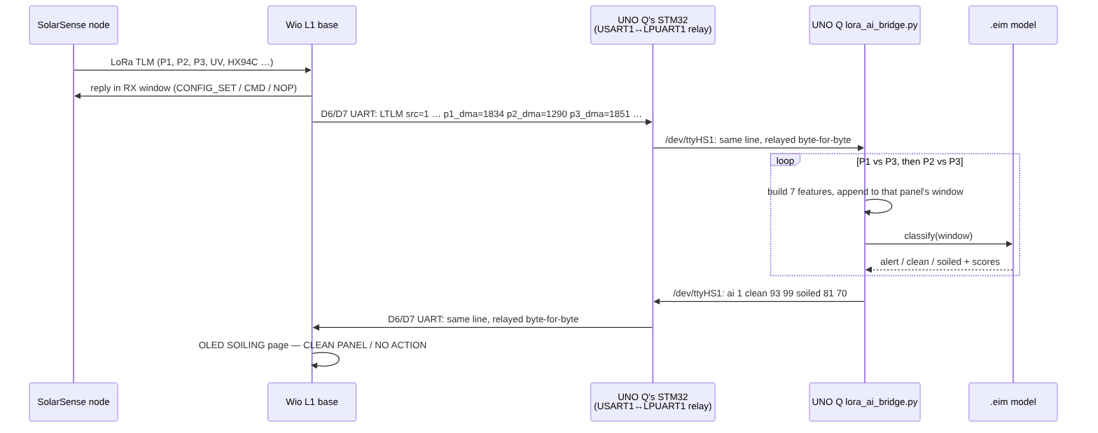
On the UNO Q, those pins belong to its onboard STM32U585 (as USART1) — the same STM32 that already receives CAN (A12 step 2, B2). I added a second mode to its firmware that copies every byte between USART1 (the L1) and LPUART1. Linux sees LPUART1 as /dev/ttyHS1 — the same port the CAN bridge uses. The two modes can’t run at the same time: the STM32 passes on either CAN data or the L1’s lines, so only one of serial_bridge.py or lora_ai_bridge.py runs at a time.
Why run the model on the UNO Q, not in the cloud? The CAN script’s classify option sends every reading to Edge Impulse’s cloud service, which needs internet for every decision. That’s not really edge AI. The UNO Q’s Linux side is a 64-bit ARM computer, so in Edge Impulse Studio I chose Deployment → Linux (AARCH64) and got one .eim file — the whole model packed into one program. Copy it over, make it executable ( chmod +x), done.
What the model needs. Seven inputs, listed inside the .eim file:
| Model input | Built from the LoRa packet | Scale |
|---|---|---|
perf_ratio | test panel current ÷ reference (P3) current — by default; --ratio power switches to power. Which one the model was trained on is still unconfirmed (B11) | — |
i_control_a | P3 current (the clean reference) | tenths-mA ÷ 10000 → A |
i_test_a | P1 or P2 current | tenths-mA ÷ 10000 → A |
uv_index | GUVA-S12SD mV | ÷ 110 mV per index |
pm25 | SEN66 PM2.5 | ÷ 10 → µg/m³ |
temp_c | HX94C (falls back to SEN66, then BMP280) | ÷ 100 → °C |
rh_pct | HX94C (falls back to SEN66) | ÷ 10 → % |
The model’s possible answers are alert, clean and soiled. The bridge builds the 7 inputs twice per packet — P1 against P3, then P2 against P3 — and judges each test panel separately.
One thing to keep in mind: A2 and the CAN script calculate the soiling ratio from power, but this script uses current by default, because the model’s other two inputs are currents. Which one the training data used is still to be confirmed (B11); switching is one setting.
Building the inputs. The core of lora_ai_bridge.py:
i_control_a = ref_dma / 10000.0
i_test_a    = test_dma / 10000.0
if i_control_a * 1000.0 < a.min_ref_ma:
    return None, "dark"          # night / heavy shade: ratio is meaningless
perf_ratio  = i_test_a / i_control_a
...
return [perf_ratio, i_control_a, i_test_a, uv_index, pm25, temp_c, rh_pct], None
The dark check matters more than it looks. At night every panel gives a few milliamps, and dividing one tiny number by another just gives noise — the model would happily call a clean panel dirty at 11 pm. If the reference panel gives less than 5 mA, the bridge doesn’t ask the model at all.
Time windows. If the model looks at several samples at once, the bridge keeps a rolling buffer for each panel and reports wait until the buffer is full. The samples are laid out in the order Edge Impulse expects — all seven inputs of sample 1, then sample 2, and so on:
buf = self.buffers.setdefault((node, panel), collections.deque(maxlen=self.window))
buf.append(feats)
...
flat = [v for s in samples for v in s]
res = self.runner.classify(flat)
scores = res["result"]["classification"]
label = max(scores, key=scores.get)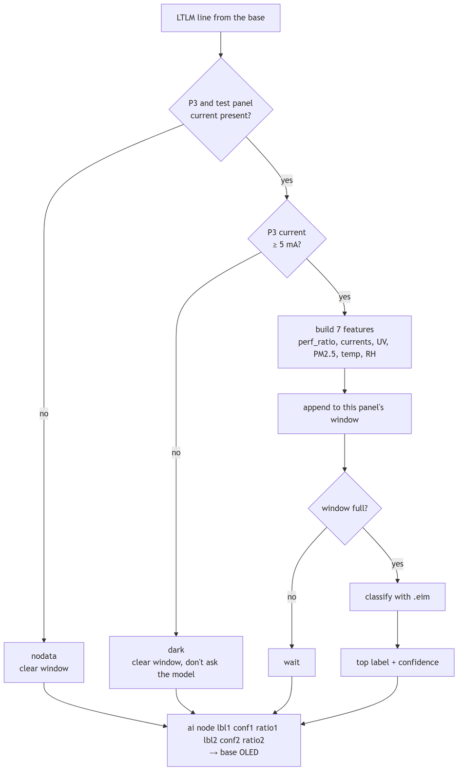
Talking to the .eim. The model file is a program that receives data as JSON over a local socket. If Edge Impulse’s Python SDK is installed, the bridge uses it. If not (its audio dependencies can be hard to install on a small board), a 50-line built-in client does the same job: start the model, send JSON, read the reply:
self._proc = subprocess.Popen([self._model_path, sock_path], ...)
...
self._sock.sendall(json.dumps({"classify": features, "id": self._id}).encode())
while True:
    chunk = self._sock.recv(4096)
    if chunk[-1] == 0:          # end of message
        data += chunk[:-1]
        break
    data += chunk
The reply to the base is one line:
cmd = f"ai {node} " + " ".join(f"{l} {c} {r}" for l, c, r in out) + "\n"
ser.write(cmd.encode("ascii"))           # e.g. "ai 1 clean 93 99 soiled 81 70"
With --csv, every decision is logged together with the inputs behind it, so I can later check the model against what the panels really looked like.
A11. Connection Explanation
Panels. The three panels go to screw terminals J1, J2 and J3. Panel 3 is the clean reference — remember which one you keep clean. Each panel’s current goes through a 0.1 Ω resistor (measured by its INA219B), then an SS14 diode.
Battery. LiPo on J4. Use a battery pack with a built-in protection circuit — see the safety note in B6.
Sensors. Thermocouple into the J8 screw terminal — mind the polarity (on a K-type, yellow is +). HX94C on J11; the 12 V boost powers it, and two 150 Ω resistors (R24, R25) turn its humidity and temperature currents into voltages. UV sensor on J13, SEN66 on J12 or J15.
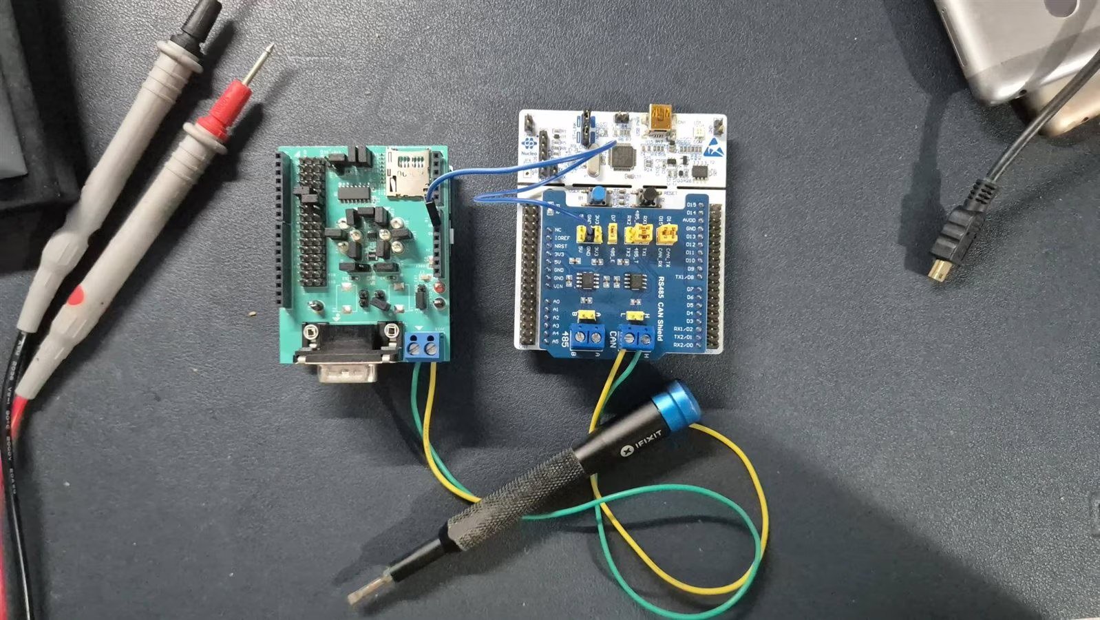
CAN. J7 carries the STM32’s CAN signals at logic level — this board has no CAN transceiver of its own. J7 goes to an external CAN transceiver board. From there, CANH/CANL run over shielded twisted-pair cable, with a shared ground, to the MAX33041ESHLD on the Arduino UNO Q. In the final build, the transceiver board is a Waveshare RS485/CAN shield on perfboard at the back of the panel mount (Fig 51). J7 pinout: 1 = 3.3 V, 2 = CAN_RX, 3 = CAN_TX, 4 = GND (A7.4).
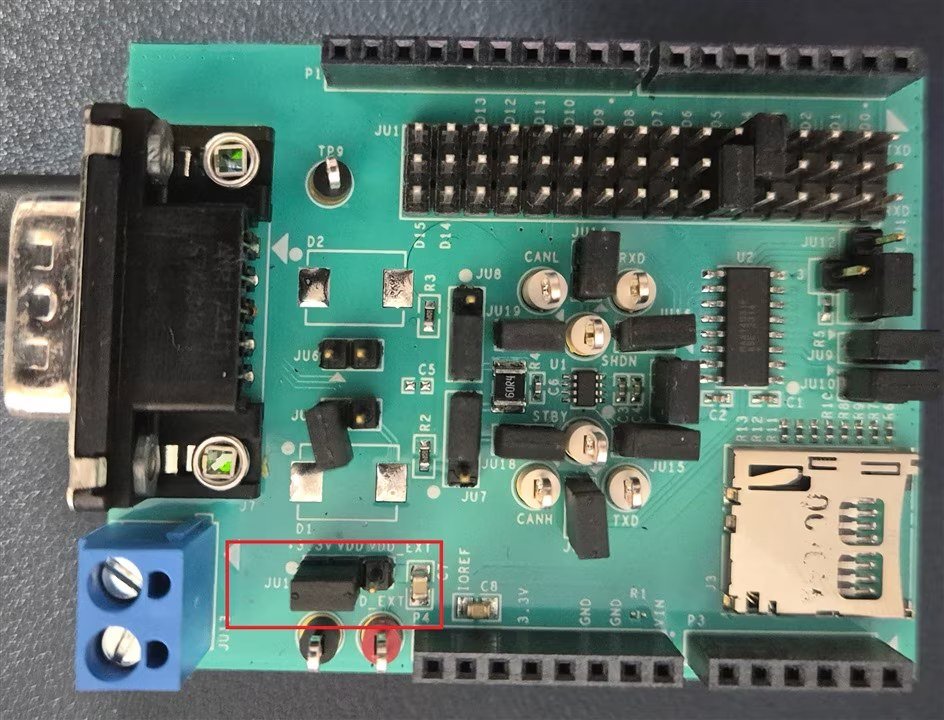
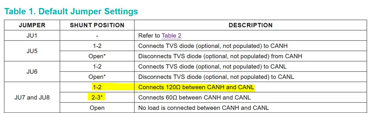
On the MAX33041ESHLD, move jumper JU11 to the 3.3 V side so it takes power from the UNO Q, and set JU7/JU8 to 1-2 (120 Ω). The default is 60 Ω; B3 explains why that matters.
LoRa. The Wio-SX1262 (U10) is on the PCB, sharing the SPI1 bus with the MAX31855, plus its reset, BUSY and DIO1 lines. The radio needs 8-bit SPI transfers and the MAX31855 driver uses 16-bit, so the radio driver switches SPI1 to 8-bit for each transfer and back to 16-bit afterwards. Always connect an antenna before powering a radio — transmitting without one can damage the SX1262 (on both the node and the Wio Tracker L1).
Wio Tracker L1 to UNO Q. No USB cable, on purpose — the UNO Q’s single USB-C port is used for power. Instead:
| Signal | L1 pin | Goes to | UNO Q header pin | STM32U585 pin |
|---|---|---|---|---|
| L1 UART TX | D6 | → | D0 | PB7 (USART1_RX) |
| L1 UART RX | D7 | ← | D1 | PB6 (USART1_TX) |
| Ground | — | shared ground | GND | — |
Both sides use 115200 baud. On the UNO Q, the STM32 copies the bytes to LPUART1, which runs at 209700 baud (not a typo — the same rate the CAN bridge link already uses; see A12 step 4).
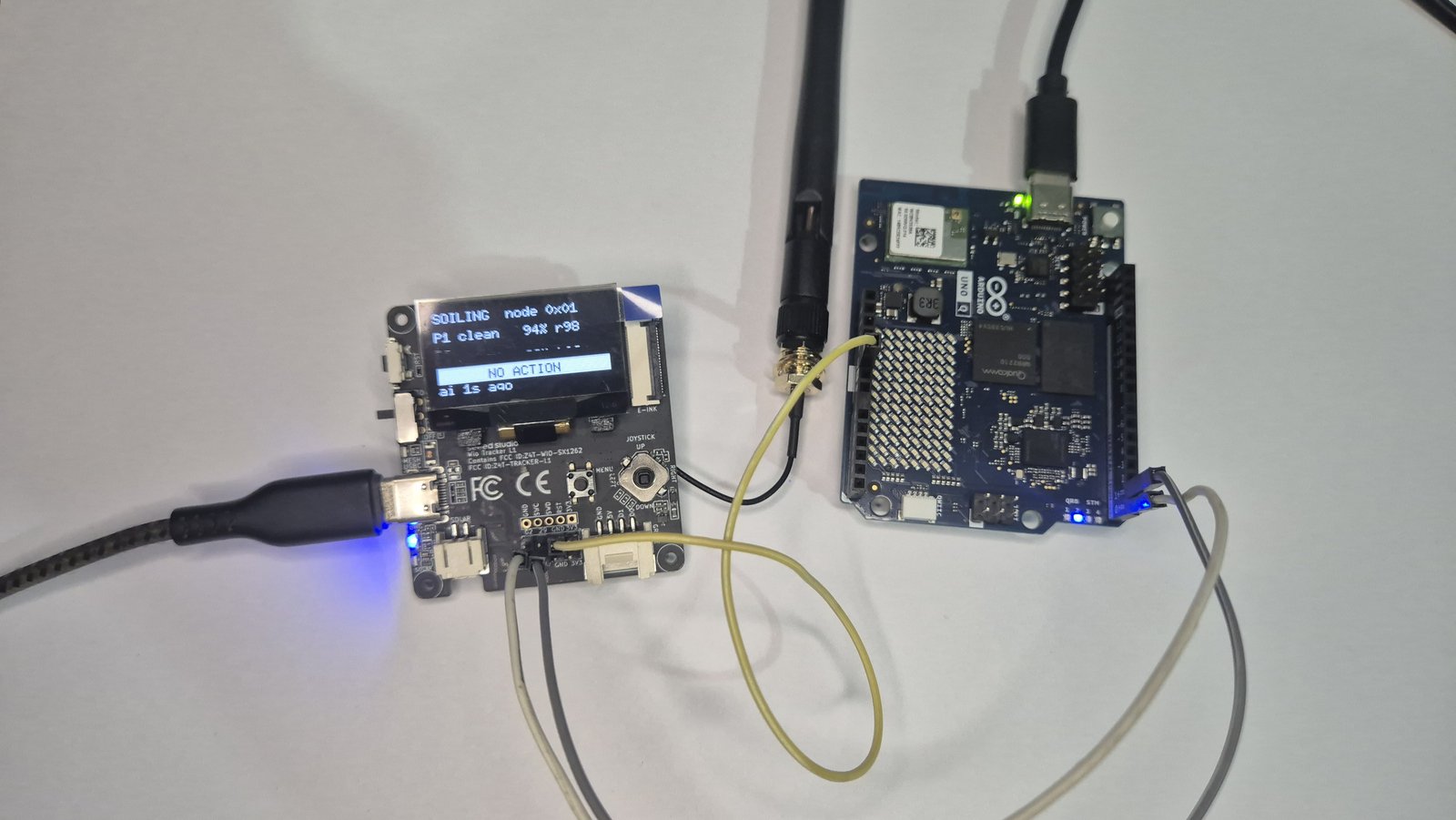
P1 clean 94% r98 , NO ACTION bar) — but that result comesfrom a test build that shows a fixed result, not yet from a real round trip through the STM32. It confirms the wiring and the screen code, not the whole data path.
STM32L476 pin map (from the firmware’s main.h and CubeMX project):
| Signal | STM32 pin | Goes to |
|---|---|---|
| SPI1 SCK / MISO / MOSI | PA5 / PA6 / PA7 | MAX31855 (U11) and Wio-SX1262 (U10), shared |
| Thermocouple chip select (TC3) | PB1 | MAX31855 U11 — the populated one (TC1 PA4, TC2 PB0 are DNP) |
| LoRa chip select | PA8 | U10 NSS |
| LoRa reset / DIO1 / BUSY | PB10 / PB11 / PB12 | U10 |
| I2C1 SCL / SDA | PB8 / PB9 | INA219B x3, MAX17048, BMP280, SEN66, OLED |
| CAN1 RX / TX | PA11 / PA12 | J7, logic level → external CAN transceiver |
| UV (ADC1 IN5) | PA0 | GUVA-S12SD, J13 |
| HX94C RH / temp (ADC1) | PA1 / PC4 | 150Ω shunts R24 / R25, J11 |
| Rain analog / detect | PC5 / PB5 | J16 (not fitted) |
| 12V boost enable | PB2 ( EN_12V ) | TPS61040 — HX94C excitation |
| Charger status CHRG / DONE | PB14 / PB15 | CN3791 |
| Fuel-gauge alert | PB13 | MAX17048 ALRT |
| microSD | PC8–PC12, PD2 (SDMMC1), card-detect PC6 | J14 |
| Debug console | PA2 / PA3 (USART2) | ST-Link virtual COM port |
Powering the Wio Tracker L1. The UART link carries only data: the readings up, and the result back down. A USB cable would also have powered the L1; the UART link doesn’t, so the L1 runs from its own USB-C supply (Fig 40). A battery or the 5 V pin would remove that second cable (B12).
A12. Setting It Up and Running It
1. The node (STM32L476).
cd solar-sense-v1-fw
make
./flash.sh            # ST-Link; add --cur if SWD won't attach after a power toggle
2. The UNO Q’s STM32 (CAN receiver and L1 relay). First take the STM32 back from Arduino’s arduino-router service (why: B2), then flash nucleo-code/qstm-can-receiver. Its firmware has a second mode that copies the L1’s serial lines (USART1, on D0/ D1) to Linux, the same way CAN data gets there. The two modes share /dev/ttyHS1, so run either the CAN bridge or the LoRa AI bridge, not both:
sudo cp /etc/systemd/system/arduino-router.service \
    /home/arduino/arduino-router.service.bak
sudo rm /etc/systemd/system/arduino-router.service
sudo systemctl mask arduino-router
sudo systemctl daemon-reload
sudo pkill -9 -f arduino-router
# reboot, then flash the bare-metal STM32U585 project
2b. The CAN bridge (UNO Q, Linux side) — this sends data to Edge Impulse. It reads /dev/ttyHS1; the port, the soiling thresholds and the reference panel are set in config.py:
cd host-software/bridge
pip install -r requirements.txt            # pyserial, requests
export EI_API_KEY=ei_xxxxxxxxxxxx          # from your Edge Impulse project → Keys
python3 serial_bridge.py
Put the node in data-collection mode ( powersave off on its console) so it sends every 5 seconds.
3. The Wio Tracker L1 base.
cd wio-base
pio run
# double-tap RESET → a "TRACKER L1" USB drive appears → copy the .uf2 onto it
Connect the L1’s D6/ D7 to the UNO Q’s D0/ D1, plus ground, as in A11 — this is the L1’s link to the UNO Q, not its USB port.
Useful base console commands: dump (settings and nodes), set wake 60, set sensors 0x1DF (HX94C off), set sf 9, cmd 1 identify, stay-awake 1 300.
4. The LoRa AI bridge (UNO Q).
mkdir -p ~/solarsense/lora-ai && cd ~/solarsense/lora-ai
# copy lora_ai_bridge.py + the model here
mv 'solar-sense-linux-aarch64-v2-impulse-#1.eim' solar-sense-v2.eim
chmod +x solar-sense-v2.eim
./solar-sense-v2.eim --print-info          # window size, interval, labels
sudo apt install python3-serial
sudo usermod -aG dialout arduino           # log out/in afterwards
# --port/--baud default to /dev/ttyHS1 @ 209700 — the STM32 relay, not a USB port
python3 lora_ai_bridge.py --no-model        # first: check the round trip, OLED should show "wait"
python3 lora_ai_bridge.py --model ./solar-sense-v2.eim --csv lora_ai.csv
To start it automatically at boot, copy solarsense-lora-ai.service to /etc/systemd/system/ and run sudo systemctl enable --now solarsense-lora-ai.
A13. Testing and Demo
This section shows what works. How each part was tested and fixed is in Part B: sensor checks in B5, battery safety in B6, the full LoRa test table in B10, and the offline test of the AI bridge in B11.
The project video is in the shared folder (link in the Video section at the top).
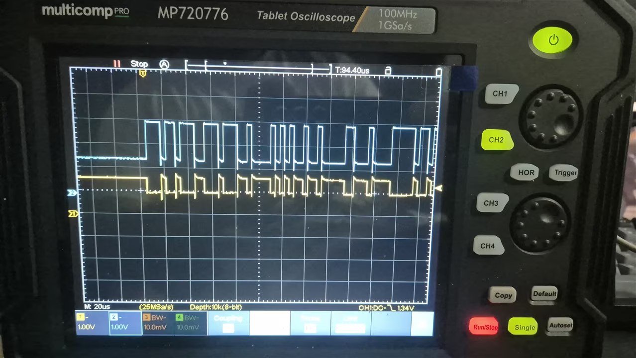
CAN working on the bench:
The panels outdoors:
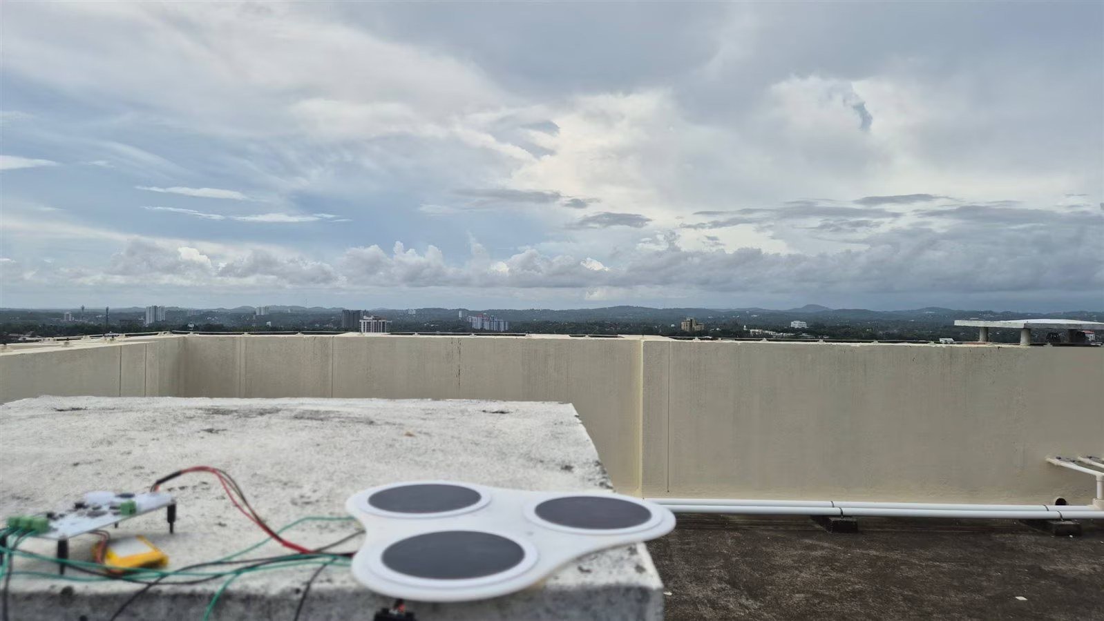
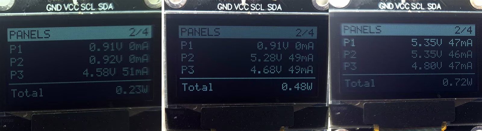
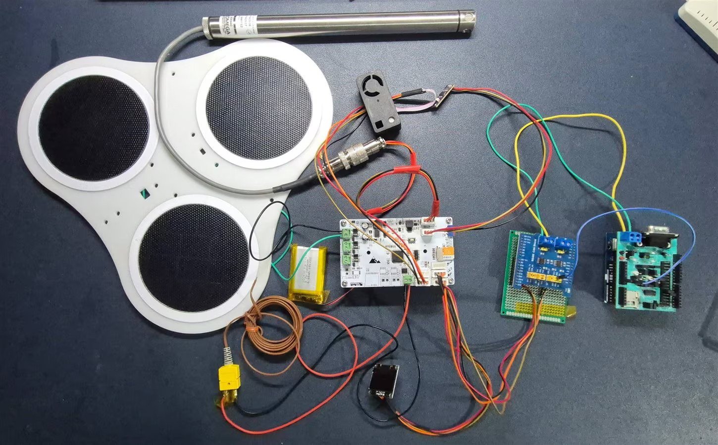
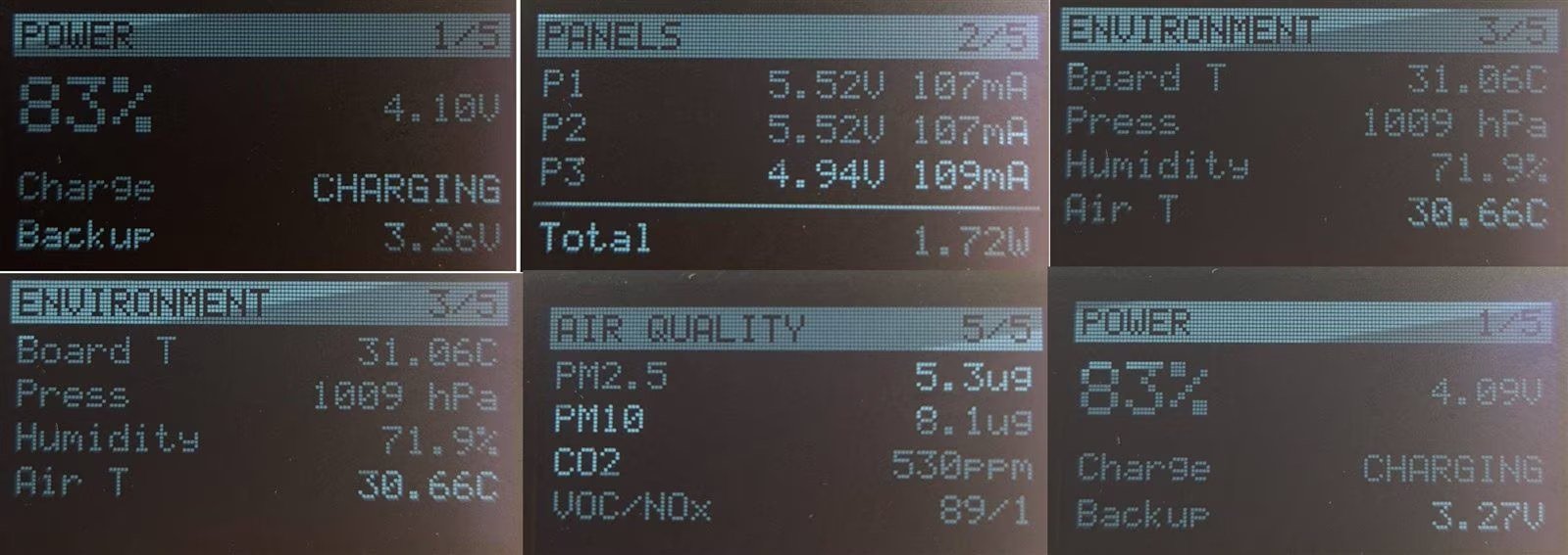
On a sunny morning at 9 am I measured 1.72 W from the three panels — more than 1 W even with one panel fully shaded. The panel surface temperature rose from 30.4 °C to 31.6 °C within seconds of direct sun, while the air only reached 30.66 °C. That’s quick proof that the thermocouple sees something different from the air.
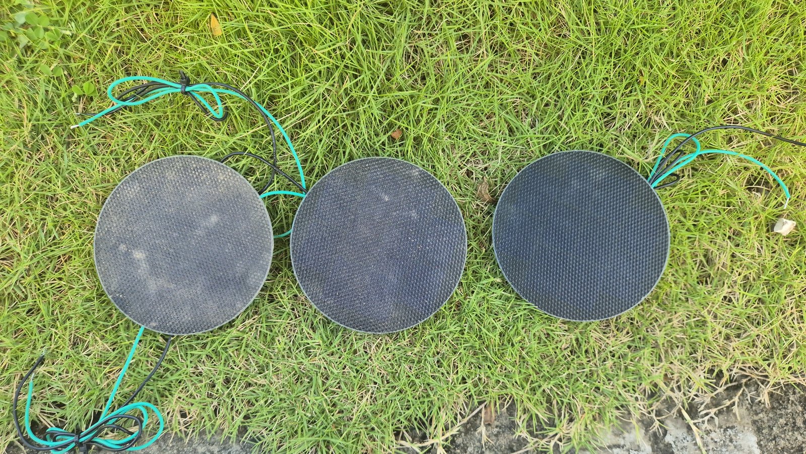
What the dust actually looks like. The soiling ratio in A2 is just a number; this is what it means. I left three panels of the same model as P1–P3 outdoors next to a busy road — not wired, not part of any measurement — just to show how dust builds up:
How the CAN data gets into Edge Impulse, and the first model:
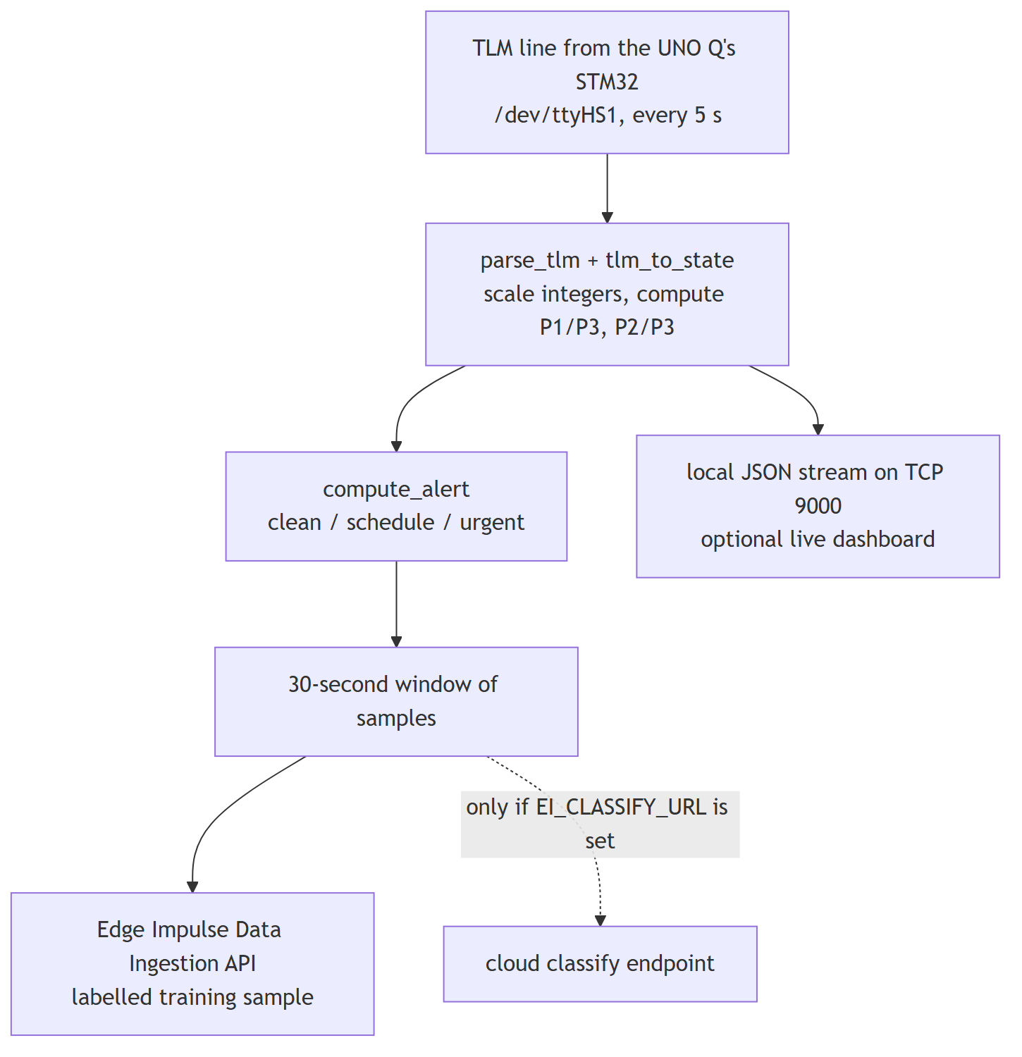
serial_bridge.py turns each CAN data line into labelled training data for Edge Impulse.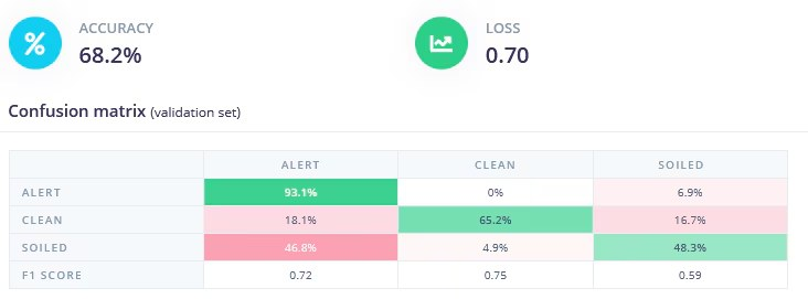
The LoRa link: one packet every 60 s at about −41 dBm signal strength on the bench. Settings changed at the base reach the node at its next wake-up, and the node sleeps in between.
The LoRa AI bridge: tested offline only so far. The results, and what they do and don’t prove, are in B11.
The final device:
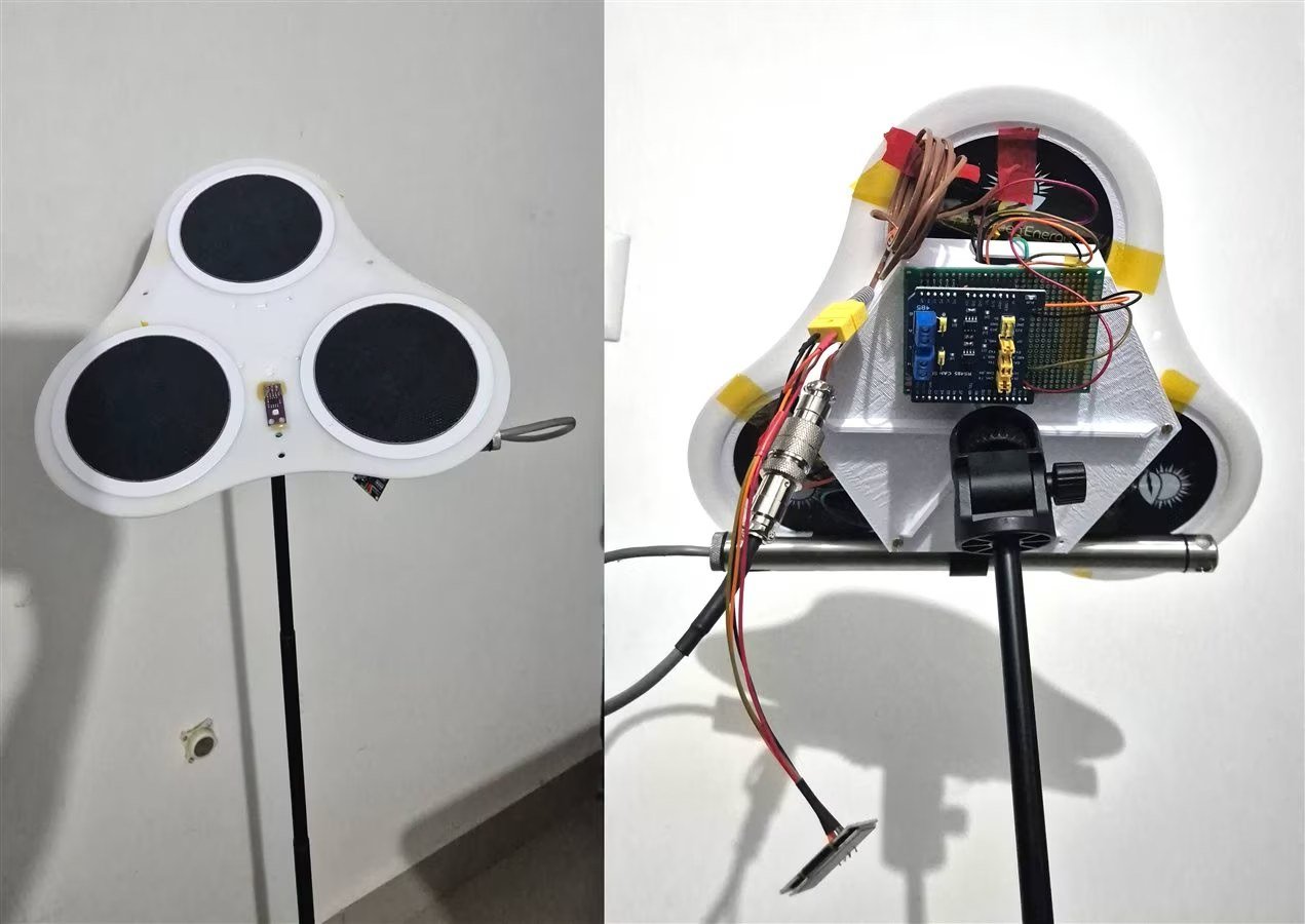
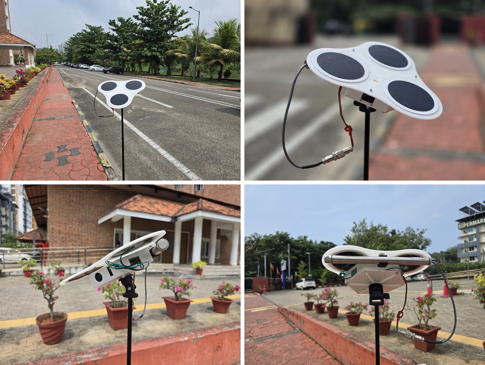
The final deployment. For the final deployment and the project video, the node went outdoors on its tripod, next to a road, with the gateway in its case (Fig 32). What has and hasn’t yet been proven live on this hardware is listed in B11 and B12.
PART B — THE DEVELOPMENT JOURNEY
B1. Where It Started
Before this project I had a rough proof of concept on a Raspberry Pi. A K-means anomaly detector reached 44% accuracy; a 3-class neural network reached 67.3% after 30 days of data. That was good enough to show the ratio idea works, but not good enough to stop there. I needed better sensors, more consistent data, and a reliable way to move it all around.
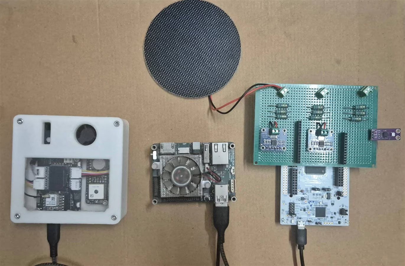
Moving the data turned out to be most of the work: an Arduino UNO Q that didn’t let me use its CAN controller, a PCB with more I²C devices than sense, three environmental sensors that each taught me something, a LoRa radio problem that turned out to be bad soldering, and an AI model at the end trying to tell dust from a passing cloud.
B2. Can Arduino CAN?
Setting up the UNO Q itself was easy: install App Lab, plug in over USB-C, click through the setup. Every new board gets the “blink an LED” test. Doing that through Zephyr (the real-time operating system Arduino runs on the UNO Q’s STM32), a Python script on Linux and a remote call between them felt like using a cannon to kill a mosquito — but it worked.
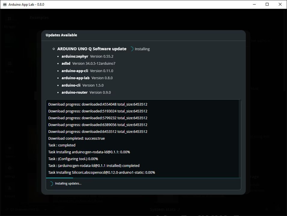
CAN was harder. The UNO Q’s STM32U585 has a CAN controller (FDCAN), but Arduino’s Zephyr-based software doesn’t make it available (an Arduino forum thread confirmed I wasn’t imagining it). My first idea was to add another board in between: Qualcomm chip → UNO Q’s STM32 → Nucleo → transceiver → bus. Ridiculous.
So I took the STM32 away from Arduino’s software completely. The Linux side talks to the STM32 over a serial port managed by a service called arduino-router. Disable that service (commands in A12), and I can program the STM32 directly with ST’s own tools and libraries (STM32CubeMX and HAL). I made a minimal project for the STM32U585AII6TR with just the serial port, an LED and the CAN controller. One catch: at 160 MHz the flash wait states must be set to FLASH_LATENCY_4 — anything lower crashes on the first cache miss.
I tested CAN in external loopback mode first: the STM32 acknowledges its own messages, so it works with nothing else on the bus:
FDCAN_FilterTypeDef sFilterConfig;
sFilterConfig.IdType = FDCAN_STANDARD_ID;
sFilterConfig.FilterIndex = 0;
sFilterConfig.FilterType = FDCAN_FILTER_MASK;
sFilterConfig.FilterConfig = FDCAN_FILTER_TO_RXFIFO0;
sFilterConfig.FilterID1 = 0x000;
sFilterConfig.FilterID2 = 0x000; // mask=0 -> accept all standard frames
HAL_FDCAN_ConfigFilter(&hfdcan1, &sFilterConfig);
HAL_FDCAN_Start(&hfdcan1);
uint8_t canTxData[8] = {0xDE, 0xAD, 0xBE, 0xEF, 0x01, 0x02, 0x03, 0x04};
txHeader.Identifier = 0x123;
txHeader.IdType = FDCAN_STANDARD_ID;
txHeader.DataLength = FDCAN_DLC_BYTES_8;
HAL_FDCAN_AddMessageToTxFifoQ(&hfdcan1, &txHeader, canTxData);
CAN OK id=0x123 d=DEADBEEF on the serial monitor, and a clean differential signal on the scope (Fig 41). Finally — the Arduino Q CAN.
B3. The Termination Resistor That Cost Me an Evening
Between a Nucleo F103 (with a Waveshare shield, 120 Ω on board) and the MAX33041E board on the UNO Q, nothing worked — messages didn’t get through. Adding a shared ground didn’t fix it (though it’s needed anyway). The multimeter showed the real problem: the Waveshare board measured 120 Ω between CANH and CANL, but the MAX33041E measured 60 Ω — its default jumper setting. A CAN bus needs 120 Ω at each end; a mismatch causes reflections that corrupt the messages. Moving JU7/JU8 to 1-2 (120 Ω, Fig 39) fixed it immediately.
B4. The Loose Screw Terminal
Once, a loose screw terminal disconnected the bus. By default ( AutoRetransmission=ENABLE), the STM32 keeps resending a message that nobody acknowledges — forever. It has only three transmit slots (“mailboxes”), so after the first three messages they were all full, and every later message — and every later heartbeat — had nowhere to go. That’s why send_frame() (A10.3) now gives up immediately instead of waiting. CAN is an extra path; a dead cable must never stop the board from measuring.
B5. Sensors, and Checking Them Without a Lab
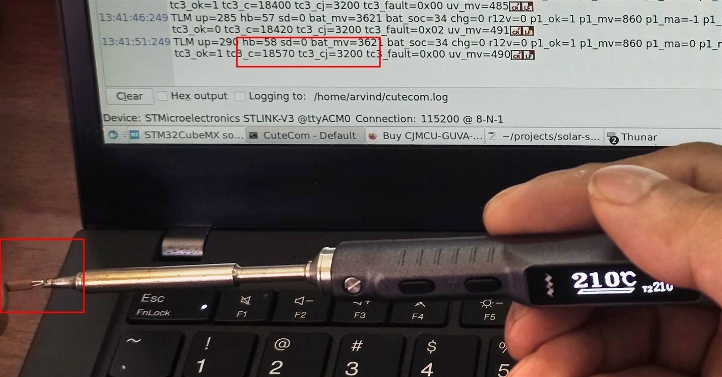
I don’t have a calibrated thermocouple reference, so I checked it against my TS101 soldering iron set to 210 °C. It read 185 °C — about right, since an iron’s tip temperature often differs from its setting. Holding the junction in my hand made the reading rise as expected. Low-tech, but reassuring.
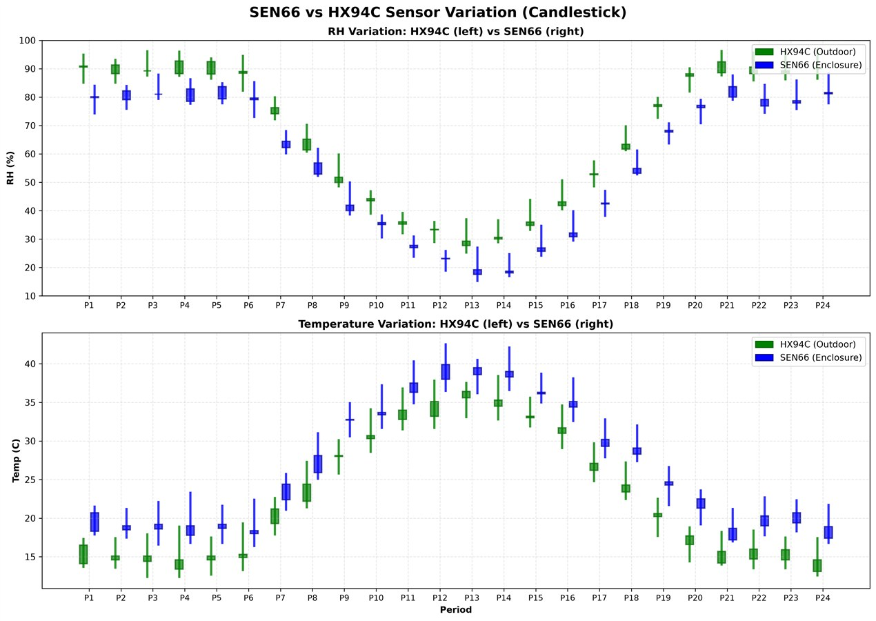
For humidity, I compared the HX94C (outdoors, on its cable) with the SEN66 (inside the box). The SEN66 reads about 10% lower humidity and about 4 °C warmer. That’s exactly what a warm, dry box should do — and both follow the same trend, so the difference is explainable, not noise. It also shows the third humidity sensor was worth adding.
B6. Safety — the LiPo Over-Voltage
Sensors, SD card and CAN all worked. Battery charging didn’t. It was night, so I powered the charger from a bench power supply instead of the panels. In its final, constant-voltage stage, the CN3791 should hold the battery at 4.2 V — but the battery voltage climbed to 4.41 V before the charger took control. That was high enough to trip the battery pack’s own protection circuit. The fuel gauge reading dropped from 4410 mV to 915 mV for a moment, then the cell recovered to a safe 4.216 V once charging stopped.
The table below is from an earlier, normal charge in the same session — not the 4.41 V event. It taught me to judge the cell by its resting voltage, not its voltage while charging:
| Condition | Reading | Notes |
|---|---|---|
| Charging (at the battery terminal) | 4.288 V | Raised by the charging current flowing through the cell’s internal resistance |
| Charger off (resting voltage) | 4.144 V | The real state of the cell — the number that matters for safety |
| Drop when charging stops | 0.144 V | Lost across the pack’s internal resistance |
| Charging current (0.1 Ω shunt) | 41.4 mV → 414 mA | Calculated. Within the expected 0.4–0.5 A; the CN3791’s current follows the input power, up to about 1.2 A (A7.1) |
| Power supply current while charging | 400 mA | Cross-check |
| Power supply current, battery removed | 22 mA | Board + charger at idle |
I haven’t found the root cause. My best guess is that the reverse-protection circuit disturbs the voltage the CN3791 senses. I can’t stress this enough: the CN3791 can push a LiPo to an unsafe voltage. Without a protection circuit the battery is a serious fire hazard, and even with one, repeated over-voltage will shorten its life. If you build this, use a protected battery pack, and build it at your own risk.
B7. First Field Data
After the first full day of real field data, the first model reached 68.2% (Fig 49, details in A10.3b), against 67.3% for the old proof of concept after 30 days. Not a big jump — but the data was already better: more sensors, and panels further from shade. Then the monsoon arrived, and for a while I didn’t trust the box to stay waterproof.
The current model (v2), and why I don’t fully trust its 99.8% yet: see A10.3b.
When the sun was too good. A problem I didn’t see coming: on some days the sun was so strong that the battery charged to full — and the next day it was still full. When the LiPo is full, the CN3791 stops charging. With nothing drawing power, the panels deliver almost no current, and the INA219s measure a few milliamps of nothing. No current means no soiling ratio — so on the sunniest days, data collection stopped. (The LoRa AI bridge would have marked those days dark for the same reason: the reference panel drops below its 5 mA threshold.)
The fix was to give the energy somewhere to go. The OLED was only meant for debugging, but I 3D printed a new version of the enclosure with the OLED permanently fitted. Now I can drain the battery by running the SEN66 (with its fan on, it’s the biggest steady load on the board) and the OLED. The battery never sits at full, the charger keeps charging, and the panels keep producing a current I can measure. Wasting energy on purpose on a solar-powered device feels backwards — but a measurable current beats a full battery. (The new enclosure is in A8.)
B8. Adding LoRa — and Three Detours Just to Boot the Base
Why LoRa at all is explained in A3. Getting the Wio Tracker L1 to run my own firmware took three detours before I even got to the radio:
1. Wrong memory layout. The board ships with Nordic’s Bluetooth stack (SoftDevice S140) version 7.3.0, but the Adafruit board package builds programs for version 6.1.1, which starts at a different memory address. My program landed inside the Bluetooth stack and never started. Don’t trust the documentation — read it from the board: enter the UF2 bootloader and open INFO_UF2.TXT. The fix was moving the program’s start address from 0x26000 to 0x27000.
2. Blank OLED. Instead of guessing, I added an i2c scan command to the console: the display was at address 0x3D, not 0x3C. Then the right edge was cut off by about 2 pixels — the classic sign of an SH1106 display being driven as an SSD1306. Changing the driver fixed it.
3. Flashing without serial-port permissions: copy the .uf2 file onto the bootloader’s USB drive. The board programs itself and restarts.
B9. The SX1262 That Wouldn’t Talk (It Was a Soldering Fault)
On the node’s first start-ups, the radio reported “init OK” but every transmission failed. Reading its registers returned a changing value — 0xA8A8 on one boot, 0x5151 on the next. A value that changes every time means the MISO line (data from the radio back to the STM32) is floating: nothing real is coming back. “Init OK” only proved the BUSY line moved; writing to a chip can’t tell you whether it heard you. So I narrowed it down step by step:
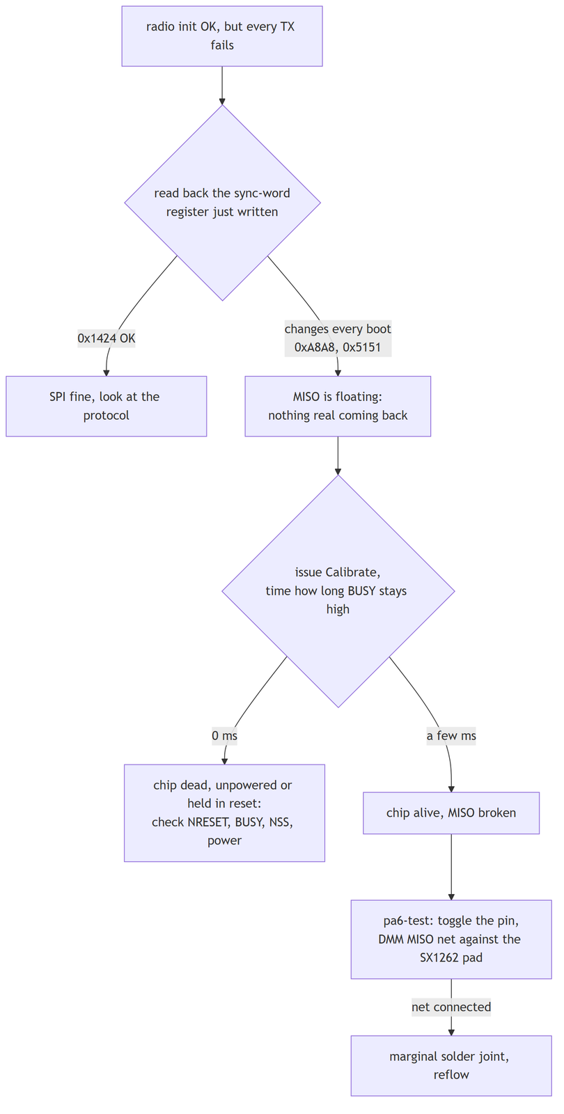
The results across repairs: busy=1ms sync=BAD (chip alive, MISO open) → after reflowing, busy=0ms CHIP-DEAD (the repair had loosened a different, good joint) → final reflow, busy=9ms sync=0x1424 OK, and transmissions completing. Cold solder joints on MISO, BUSY and DIO1. Those checks stayed in the firmware as a health report at every start-up. Lesson: before trusting a new SPI driver, read back at least one known value — a driver that only writes will happily report “OK” to a dead chip.
B10. Four More LoRa Bugs
The base replied before the node was listening. Once the radio worked, every 60-second packet arrived (signal about −41 dBm). But the node never heard the base’s reply: RX window empty, every time. The base sent its reply about 30 ms early — just before the node opened its listening window — so the start of the message was already gone. The fix is the 200 ms margin in A10.4: open early, stay open late.
Enabling a sensor that isn’t there. CONFIG_SET rejected -13. The base was sending settings that switched on the SEN66, which wasn’t fitted on that test node, and the node (correctly) refused them. The fix is the sensor check in A10.5. The base also has to compare against the checksum of those trimmed settings — otherwise it keeps resending settings the node already has, forever.
The SF12 airtime bug. This one took hours. At SF12 (the slowest, longest-range setting), every transmission failed — and the radio was still genuinely transmitting when the software gave up ( irq=0x0000 st=0x62, chip still in transmit mode). First I found the transmit timeout was fixed at 2000 ms, too short for a 2.5 s packet, and wrote tx_timeout_ms(). It still failed.
Then I checked lora_airtime_ms() itself. The coding-rate factor was (cr − 4) where it should have been cr: the code already stores the coding rate as 5 for “4/5”, so subtracting 4 made the payload part of the calculation 5 times too short:
/* before */  int payload_symb = 8 + ceilv * (cr - 4);   /* 4/5 → ×1  */
/* after  */  int payload_symb = 8 + ceilv * cr_mult;   /* 4/5 → ×5  */
For a 55-byte packet the buggy code said 1024 ms; the real answer is 2466 ms. At SF7 the error is only tens of milliseconds and hides inside any safety margin; at SF12 it decides whether it works at all. Because this function is shared, the same bug also made the base’s “does this setting fit the listening window” check too lenient — one fix in lora-link corrected both. After the fix:
LORA RX CONFIG_SET → CONFIG applied ... on probation (on trial — see Fig 58) → LORA TX TLM mask=0x07F 46B →
LORA PHY confirmed (downlink heard on new PHY) — a full round trip at SF12, for the first time.
The base stopped hearing its own settings change. When I typed set sf 12, the base switched its own radio to SF12 immediately — before it had sent that change to a node still using SF9. So it could never hear the packet it needed in order to deliver the change. Now the base sends the new settings using the old radio settings, and switches only after that message has gone out.
Changing radio settings safely. A wrong spreading factor or transmit power is the one setting that can make the node unreachable. So any radio change is on trial first:
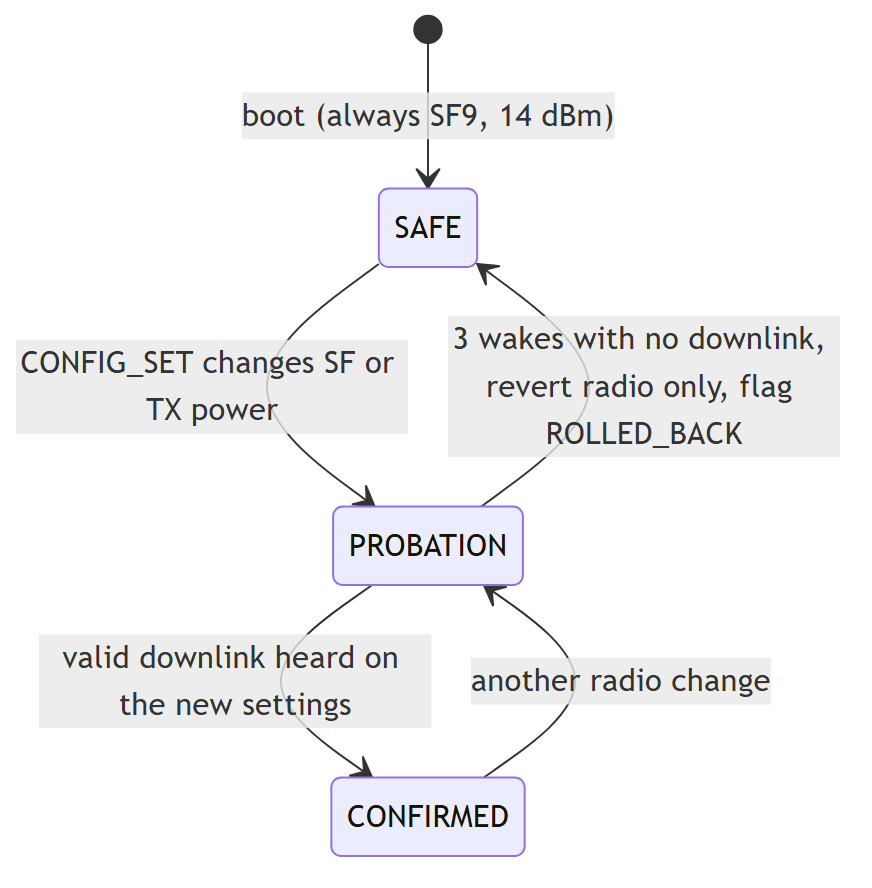
I tested it by deliberately setting a spreading factor the node couldn’t use. Both sides went back to SF9 and found each other again.
| LoRa check | Result |
|---|---|
| SX1262 SPI read-back | sync=0x1424 OK , busy=9ms |
| Node packets every 60 s | base decodes every packet, about −41 dBm on the bench |
| Base reply arrives in the node’s listening window | RX CONFIG_SET rssi=-41 snr=10 |
| Settings update | CONFIG applied v1 → steady RX NOP |
| Switch HX94C off remotely | packet sensor mask 0x07F → 0x05F , 12 V supply cut |
| STOP2 sleep, 60 s wake-ups | one exchange per wake-up, no watchdog resets during sleep |
| Settings survive a reset | LORA cfg restored v14 ... (PHY->SAFE) |
| Bad spreading factor rolled back | both sides back to SF9, connected again |
| SF12 end to end | confirmed, with the listening window raised to 2800 ms |
| Shared SPI with the MAX31855 | thermocouple still reads correctly |
Not done yet: measuring the real sleep current (I had no ammeter in line on the bench — sleep is confirmed by the logs, not by a meter), and a proper range test with the node on the terrace.
B11. The LoRa AI Bridge — What I Found, and What’s Still Unproven
The plan was USB — but the UNO Q has only one USB port, and it’s taken. The original design connected the Wio Tracker L1 to the UNO Q with a USB cable. But the UNO Q has exactly one USB-C port, and it must stay on power. I considered Bluetooth first (both boards have it), but for two boards a few centimetres apart that meant a lot of new work — a Bluetooth service on the L1 and a rewrite of the bridge script — for a link that doesn’t need to be wireless. A wired serial link is simpler, and I had a spare pair of pins: the L1’s D6/ D7 ( Serial1), meant for a GPS driver that doesn’t exist yet.
The catch was on the UNO Q side. Its header pins (including D0/ D1) connect to its STM32U585, not directly to the Linux processor, so any data has to pass through that microcontroller. Since I had already replaced Arduino’s STM32 firmware with my own for the CAN receiver (B2), I added USART1 ( D0/ D1) to that project and copy bytes to and from LPUART1 ( /dev/ttyHS1 on Linux) in an interrupt. The STM32 doesn’t read the data at all — it just passes it on (A10.6).
One consequence: the CAN bridge and the LoRa AI bridge now share the same STM32 and the same /dev/ttyHS1, so only one can run at a time — whichever mode is flashed is the live one. That’s fine for one demo unit. Running both at once would need either a second serial port to its own /dev/ttyHS*, or one program on Linux that reads the port and splits the lines by their start ( TLM vs LTLM).
The model didn’t want what I thought it wanted. I assumed the model would take the six inputs my CAN script was sending ( panel1_ratio, panel2_ratio, uv_index, aqi, humidity, temp). It doesn’t. An .eim file carries its own description, and reading the text strings out of it gave me the real input list — perf_ratio + i_control_a +
i_test_a + uv_index + pm25 + temp_c + rh_pct — and the labels alert, clean, soiled. That’s where the table in
A10.6 comes from. Lesson: read the model’s inputs from the model, not from your memory of the project.
Offline test. Before using the hardware, I tested the bridge’s logic on my PC. I fed it LTLM lines in exactly the format the base prints, with a stand-in for the model that says “clean” above a ratio of 0.9 and “soiled” below, and a window of 3 samples:
| Input | What the bridge sent back to the base |
|---|---|
| Packet 1, P1 at 0.99 of the reference, P2 at 0.70 | ai 1 wait 0 99 wait 0 70 — window still filling |
| Packet 2, same | ai 1 wait 0 99 wait 0 70 |
| Packet 3, same | ai 1 clean 80 99 soiled 80 70 — first result |
| Night reading, reference at 1.2 mA | ai 1 dark 0 0 dark 0 0 — no result, buffers cleared |
It also warned, once, that the packet had no PM2.5 value (the test node has no SEN66) and that it was using 0 instead. That warning is deliberate: a model given a fake “perfectly clean air” value will still give a confident answer, and I’d rather it complain than be quietly wrong.
What this doesn’t prove yet. It proves the parsing, the per-panel windows, the dark check and the reply format. It doesn’t prove the real .eim agrees with my stand-in, and the base firmware changes haven’t been flashed to the board yet. Three things still need checking against how the training data was made:
perf_ratio— I’ve assumed test current ÷ reference current, since the other inputs are currents. If the training data used power, it’s one setting (--ratio power).- Window length — the rate is already right (one sample a minute, one packet a minute). The window length is stored in the
.eim, and the bridge reads it at start-up; until that many packets arrive, it showswait. I haven’t yet confirmed the value on the UNO Q with--print-info. - PM2.5 — either the SEN66 goes back on the node, or I retrain without it.
One known gap: a missed packet doesn’t reset the window yet — only a dark reading or a missing panel does — so a window can stretch across a gap. I’ll tighten that once I see how often it happens in the field.
B12. What’s Left
- Flash the updated STM32 relay firmware and the updated base firmware, and confirm an
LTLMline really travels from the L1’sD6/D7to/dev/ttyHS1. The L1 code compiles, but the wired path hasn’t been run end to end on hardware yet. - Power the L1 from a battery or the 5 V pin instead of its own USB-C supply, so the case needs one cable instead of two (A11).
- Decide how the CAN bridge and the LoRa AI bridge share the one STM32 and
/dev/ttyHS1— a script that switches modes, or a second serial port — so switching between them doesn’t need re-flashing. Run the LoRa AI bridge with the real.eimon the UNO Q, confirmperf_ratioand the window length match the training data, and compare its decisions with the CSV log and the real panels. - Measure the node’s real sleep current, and combine the SEN66 and STM32 sleep modes into a proper power budget.
- Connect the rain sensor (already routed on the PCB).
- Give the v2 model a real test set — whole recordings it never trained on — to check its 99.8% on days it hasn’t seen.
- Send the result one step further — back over LoRa to the node — so a cleaning robot next to the panels could act on it. The protocol already has room for this (a
THRESHOLDevent and a command). - A range test with the node on the terrace, and making sure the enclosure is truly waterproof (it’s monsoon season).
B13. Final Notes
I managed to stitch all these sensors together within the timeline, get real field data out of it over CAN, and then cut the cable with LoRa. Using both links was the right call: CAN for the large volume of training data, and LoRa for the daily “should I clean this panel?” question once you know what to look for — with the same UNO Q learning from one and answering over the other. Once the real model is running on it, I’m looking forward to a small OLED on my desk saying CLEAN PANEL because a model decided so, not a calendar. This project is exactly what I enjoy: STM32 firmware, environmental sensing tied to my own research, and data that may well end up in a journal paper.
Schematics
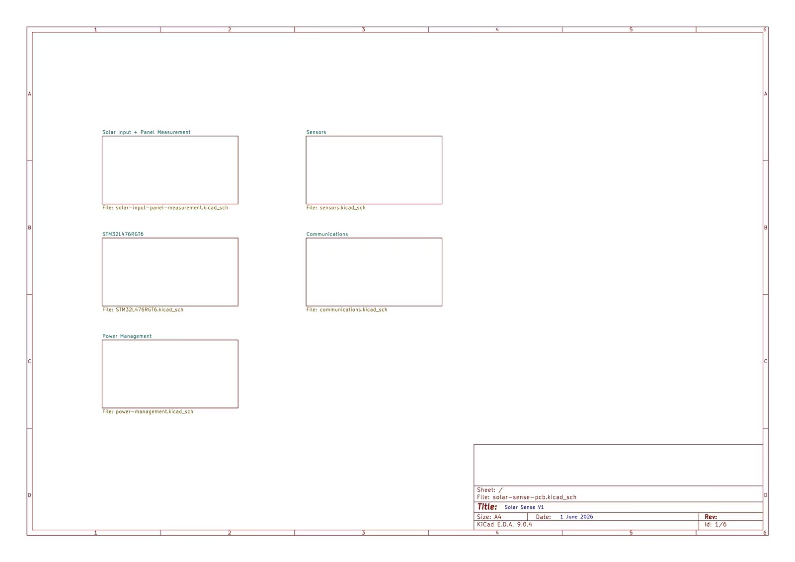
The five full sheets, as exported from KiCad. Sections A7.1–A7.5 explain each block; the board-level block diagram is Fig 9 and the system overview is Fig 6. The KiCad project is in the shared folder under solar-sense/solar-sense-pcb/.
Project Video and Source Code:
The final project video is in the public shared folder: SolarSense — shared project folder (Google Drive)
Tthe solar-sense/ folder holds all the code and the KiCad project, laid out as in A9; cad/ holds the STEP and 3D-print files; data/model/ holds the trained Edge Impulse model.
Edge Impulse project (public): Solar sense — the training data and the model (A10.3b).
