




A Dual-Architecture Vision-Free and Privacy-First Autonomous Vacuum with TinyML Predictive Maintenance and Sensor Fusion Navigation . Most robot vacuums today suffer from three major issues: they are expensive, they rely on privacy-invading cameras to navigate, and they fail suddenly without warning. My project, A Vision-Free Autonomous Vacuum with Edge AI Predictive Maintenance, solves this by building a custom, affordable floorcare robot from scratch that prioritises privacy, longevity, and human-robot interaction.
The project relies entirely on the dual-brain architecture of the Arduino Uno Q to keep costs down, It breaks down into three main features:
Privacy-First Navigation: Instead of mapping homes with cameras, the robot uses a completely vision-free sensor stack. A standard 2D LiDAR handles room mapping, while a “virtual bumper” made of Time-of-Flight (ToF) and ultrasonic sensors detects low-lying clutter (like cables) and transparent obstacles (like glass). The Linux side of the Uno Q handles the heavy ROS 2 navigation stack seamlessly.
Predictive Maintenance via Edge AI: To stop the vacuum from acting like a disposable appliance, the Uno Q’s real-time microcontroller will monitor inline current sensors attached to the motors. A local TinyML model will learn the normal electrical “effort” required to clean. If a brush starts to tangle or a filter clogs, the AI detects the subtle shift in current and warns the user long before the motor burns out.
Standard vacuums just beep cryptic error codes. Drawing from my background in kinetic art, I am programming the vacuum to communicate through organic movement. If the predictive maintenance model detects a jammed brush, the robot will do a quick “frustrated shake” and shut down. If the ToF sensors spot a new obstacle, it will slow down and do a cautious “investigative” arc. It is a smarter, friendlier way for the hardware to tell the user what it needs.

Component List:
| ID | Name | Quantity |
|---|---|---|
| 1 | Arduino UNO Q | 1 |
| 2 | L293D Motor Driver/Servo Shield for Arduino | 2 |
| 3 | VL53L0X Laser ToF Distance Ranging Sensor | 1 |
| 64 | DC5V 5015 Oil Containing Cooling Fan with XH2.54- 2P 12CM Cable Size:50*50*15MM | 1 |
| 5 | MINI 3PI Car N20 Caster Robot Ball Wheel, Small Robotics Wheel | 1 |
| 6 | 43–75 RPM Strong Magnet BO Motor – Single Shaft with Rubber wheels | 2 |
| 7 | TowerPro SG90 Mini Servo – 180 degree Rotation – Standard Quality | 1 |
| 8 | DMEGC INR18650-26E 3.7V 2600mAh Li-Ion Battery | 2 |
| 9 | 2 x 18650 BLM Cell Box with Wire without Cover with On/Off Switch | 1 |
| 10 | Custom 3D printed chassis | 1 |
| 11 | 10000 mAh Power Bank | 1 |
| 12 | USB-C cable | 1 |
Project Explanation Step By Step
I built the Cleo prototype robot with the components in the project inventory. I changed the original design because of hardware limits and missing components. This document explains the system that I built. It also explains the exact technical reasons why I could not implement the initial proposal.
Step 1: Drive System, Suction, and the Timer Conflict
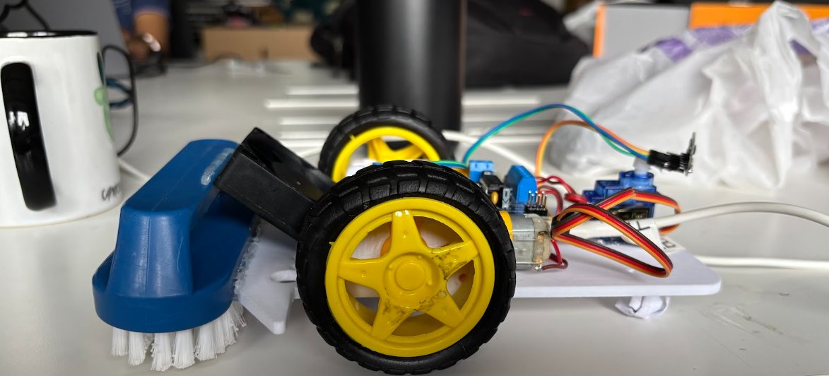
I assembled the robot chassis with two direct-current gear motors and one caster wheel. An L293D motor driver shield attaches to the Arduino Uno Q. The shield powers the two drive motors and one 5-volt centrifugal blower fan for dust collection. Two lithium-ion batteries supply direct current through a mechanical switch. During software development, I found a hardware timer conflict on the microcontroller. The servo library disabled pulse-width modulation on the motor control pins. To solve this problem without extra hardware, I used digital switching commands to operate the motors at full speed.
Step 2: Obstacle Detection and LiDAR Omission
The original proposal included a 360-degree laser LiDAR sensor and ROS 2 mapping software. I could not implement the LiDAR system for three technical reasons. First, a commercial LiDAR sensor exceeded my project budget. Second, the LiDAR sensor consumed more electrical current than my lipo battery supply could provide without voltage drops. Third, the ROS 2 software stack required drivers that were not compatible with my rapid test schedule. Instead, I installed a VL53L0X laser Time-of-Flight sensor on an SG90 servo motor. The servo rotates the sensor across 180 degrees. This configuration provides reliable obstacle distance data at low cost and low power.
Step 3: Anomaly Detection and Edge AI Omission
The initial plan proposed INA219 current sensors and an Edge Impulse TinyML model for predictive mechanical maintenance. I could not build this system because INA219 current sensors were not available in my hardware stock. Without real physical sensors to measure motor electrical load, I could not record training datasets or train a neural network model. To replace this feature, I wrote an algorithmic anomaly detector in Cleo_MVP.ino. The microcontroller saves the last twenty distance measurements in memory. If distance variance remains below 50 millimeters for ten seconds during drive mode, the software identifies that the robot is physically trapped.
Step 4: Kinetic Movement and Microcontroller Firmware
The microcontroller firmware controls robot movement through a deterministic state machine. During autonomous mode, the robot drives forward while the servo sweeps the distance sensor. When an obstacle is closer than 250 millimeters, the robot stops and inspects the obstacle path. If the anomaly detector flags a stall condition, the robot enters an alert state. The robot halts the drive motors and shakes the sensor servo rapidly from side to side. The robot then reverses for one second, turns right, and resumes forward cleaning.
Step 5: Dual-Architecture Bridge and Web Control
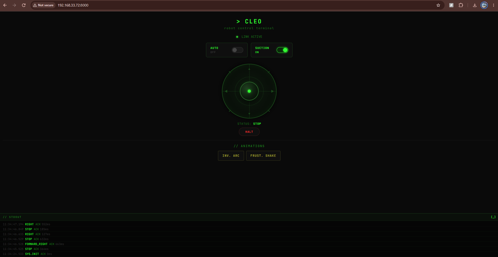
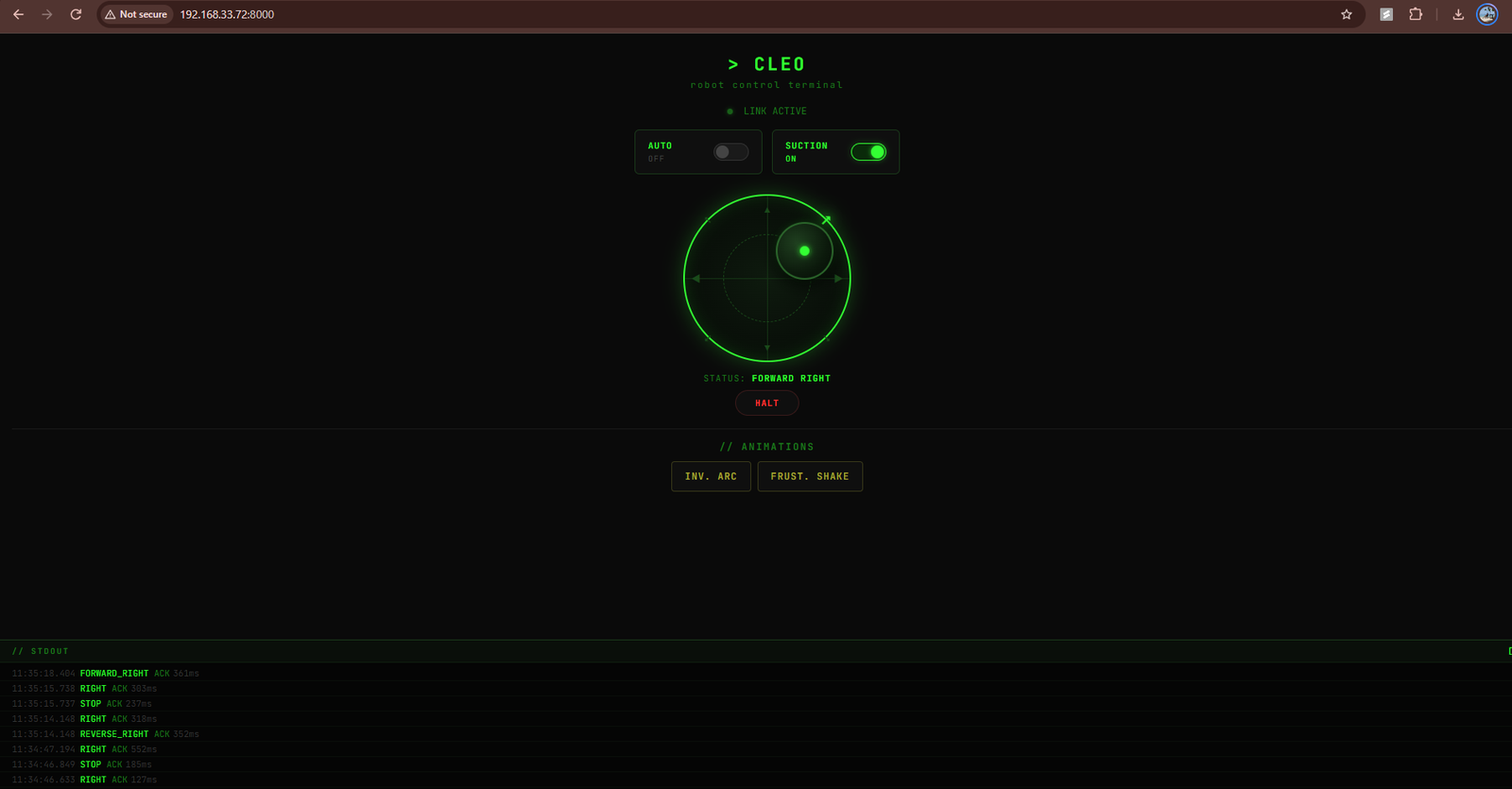
I implemented the dual-architecture communication between the Linux processor and the microcontroller. The Linux processor runs the Python web application in control_server.py. The Arduino Router Bridge library links both processor cores through remote procedure calls. The web server provides an interface for network operators. The operator can view system telemetry, control wheel directions manually, toggle the suction fan, and switch between manual and autonomous modes.
Coding Explanation and Configuration
This project is Cleo. Cleo is a dual-architecture autonomous vacuum robot. The hardware uses the Arduino Uno Q board. This board contains a Linux microprocessor and an STM32 real-time microcontroller. The Linux processor manages network communication and the user interface. The microcontroller controls the motors and reads sensor data. Both processors exchange data through an internal Remote Procedure Call bridge.
Microcontroller Firmware Explanation
The microcontroller code is in Cleo_MVP.ino. The setupMotors function configures the control pins for an Adafruit L293D motor shield. The runMotor function sets motor direction through an integrated shift register. Motor 1 and Motor 2 drive the wheels with inverted polarity. Motor 3 operates the centrifugal suction blower fan. The firmware writes digital values to the speed pins. This prevents hardware timer conflicts with the servo library.
Obstacle Avoidance Logic
Obstacle detection uses a VL53L0X Time-of-Flight distance sensor and an SG90 servo motor. The updateServo function moves the sensor between 0 degrees and 180 degrees. The runAutonomousLogic function operates a two-state machine defined by RobotState. In the driving state, the robot moves forward until the sensor detects an obstacle within 250 millimeters. In the reversing state, the robot reverses for at least 1200 milliseconds. The robot returns to the driving state after the obstacle clears.
Bridge Remote Procedure Call Interface
The microcontroller sketch exports functions to the Linux system through the bridge library. The setup function registers commands with the bridge. Movement commands include rpcForward, rpcReverse, and rpcStop. Mode functions include rpcToggleMode and rpcToggleSuction. Animation functions rpcTestShake and rpcTestArc move the servo to show status feedback. The loop function calls Bridge.update() continuously to execute incoming calls.
Linux Control Server Explanation
The Linux application code is in control_server.py. The ThreadedTCPServer class starts an HTTP server on port 8000 using start_http_server.
The RobotControlHandler class serves an HTML terminal interface with a virtual joystick. When a user inputs a movement, the server executes Bridge.call from bridge.py. A background thread processes HTTP requests. The main thread runs App.run() to keep the bridge connection active.
Hardware Configuration
Hardware connections follow the list in BOM.txt and mvp_plan.md. Install the L293D motor shield onto the header pins of the Arduino Uno Q.
Connect the VL53L0X Time-of-Flight sensor to the I2C bus pins. Connect the signal wire of the SG90 pan servo to digital pin 10. Connect the left and right drive motors to Motor Port 1 and Motor Port 2. Connect the 5V blower fan to Motor Port 3. Use two 3.7V lithium-ion cells in series to supply power.
Software Configuration and Startup
Configure and start the software on both system processors. Open Cleo_MVP.ino in the Arduino development application. Compile and flash the sketch to the microcontroller. Open a terminal session on the Linux processor of the Arduino Uno Q. Go to directory linux_app. Run the server with python3 control_server.py. Open a web browser to port 8000 to operate the robot.
Operational Parameters Configuration
The source files contain parameters for operational tuning. In Cleo_MVP.ino, adjust obstacleThreshold at 250 millimeters to set the detection range. Adjust MIN_REVERSE_DURATION at 1200 milliseconds to set the reverse escape duration. Adjust the sweep delay at 50 milliseconds to change the servo scanning speed. In control_server.py, change PORT to modify the web port. Adjust maxRadius and deadzone in the client script to calibrate joystick sensitivity.
Testing
Integration testing will begin by verifying the remote control interface. First, manual steering response will be assessed via the virtual joystick. Next, observe the command window.
Hardware and Component Testing
Test individual hardware components before full system operation as outlined in mvp_plan.md. Open the serial monitor at 115200 baud to verify the initialisation sequence in setup. Make sure that the sensor initialisation does not return an error message for the VL53L0X sensor. Test the servo movement and motor reflexes with rpcTestShake and rpcTestArc in Cleo_MVP.ino. Verify that the suction fan starts when you enable motor port 3. Make sure the wheels rotate in the correct direction for forward motion.
System Integration and Autonomous Testing
Complete integration testing through the web interface in control_server.py. Move the virtual joystick on port 8000 to verify manual steering response. Inspect the command log on the interface to confirm received signals and latency. Switch the mode toggle to start runAutonomousLogic. Place an obstacle within 250 millimeters of the front sensor during movement. Make sure that the robot stops, reverses for at least 1200 milliseconds, and turns away safely.
Schematics/Connections
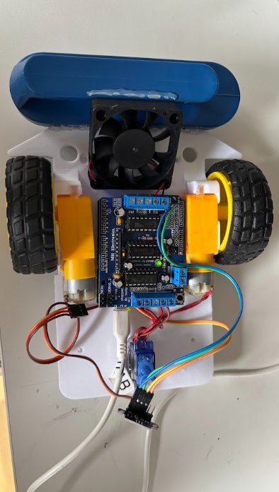
The wiring schematic uses pin assignments defined in setupMotors in Cleo_MVP.ino. Install the motor shield directly onto the Arduino Uno Q header pins. Connect the left motor to screw terminal M1 and the right motor to screw terminal M2. Connect the 5V suction fan to screw terminal M3. Connect the SG90 servo signal wire to digital pin 10 defined by servoPin, with power to 5V and ground to GND. Connect the VL53L0X sensor pins to the hardware SDA, SCL, 5V, and GND pins.
Project Videos and Source Code: click here
GitHub Link: click here
