AIDesk is an Edge AI-powered smart workspace assistant that combines computer vision, environmental sensing, health monitoring, and IoT automation to create an intelligent and adaptive workspace. The system is designed to improve user productivity, comfort, and overall well-being by continuously understanding both the user’s physical condition and the workspace environment.
Component List
| ID | Name | Designator | Qty |
|---|---|---|---|
| 1 | Arduino UNO Q (4 GB / 32 GB, ABX00173) | MCU1 | 1 |
| 2 | USB Webcam | CAM1 | 1 |
| 3 | 3.5″ SPI TFT Display (KMRTM35018, ILI9488) | LCD1 | 1 |
| 4 | 5 mm LED — Red | LED1 | 1 |
| 5 | 5 mm LED — Green | LED2 | 1 |
| 6 | 5 mm LED — Amber | LED3 | 1 |
| 7 | Passive Buzzer | BZ1 | 1 |
| 8 | 40×10 mm Cooling Fan (5 V DC) | FAN1 | 1 |
| 9 | USB-C Hub (3-in-1 Type-C dock) | HUB1 | 1 |
| 10 | 3D-Printed PLA Enclosure (wedge/StandBy style) | ENC1 | 1 |
| 11 | 220 Ω Resistors (for LEDs) | R1–R3 | 3 |
| 12 | Jumper Wires / Dupont Cables | — | — |
Project Explanation Step By Step
DeskSense is an on-device AI desk wellness companion that monitors focus, posture, and distraction entirely on an Arduino UNO Q — with no cloud connection and no data leaving the board. A USB webcam feeds a real-time computer vision pipeline. The system detects whether the user is present, checks posture against a calibrated baseline, tracks eye gaze, and flags phone-in-hand distraction. Feedback is immediate and physical: a colour LED changes, a buzzer nudges the user, and a 3.5″ TFT display shows the live state. A FastAPI web dashboard streams live scores and session history to any browser on the local network.
The Arduino UNO Q’s dual-brain architecture makes this possible. The QRB2210 (quad-core Cortex-A53 @ 2 GHz) runs Debian Linux and handles all AI inference via Arduino App Lab. The STM32U585 MCU (Cortex-M33 @ 160 MHz) drives the LEDs, buzzer, and TFT display in real time. They communicate over the Arduino RPC bridge library (Arduino_RouterBridge.h).
Step 1: Vision Pipeline Setup
The vision pipeline runs under Arduino App Lab with Agentic Mode enabled. Person and phone detection uses the App Lab Object Detection Brick (YOLOX-Nano). Face detection and gaze tracking use OpenCV’s cv2.dnn module with the pre-installed res10 SSD Caffe model (primary path) and a Haar cascade fallback. Posture is estimated by comparing facial landmark positions against a user-calibrated baseline captured at session start.
Note: Do not attempt to install opencv-python-headless via pip under App Lab’s UV_CONSTRAINT — it will fail. Use the board’s pre-installed OpenCV.
Step 2: Scoring Engine and States
Feature vectors from each frame feed a scoring engine running every second. Exponential moving averages (EMA) smooth the raw signals: α = 0.4 for engagement and α = 0.25 for posture. A dwell-time hysteresis gate (12–19 s) prevents rapid state flapping before a physical nudge fires.
| State | Trigger Condition | Physical Output |
|---|---|---|
| Focused | Engagement ≥ 88, present, good posture | Green LED, TFT green badge |
| Distracted | Phone detected, or look-away confirmed (−40 pt) | Amber LED + buzzer |
| Bad Posture | Posture score < 88, sustained 12–19 s | Red LED + buzzer, TFT alert |
| Absent | No person detected > ABSENCE_TIMEOUT_SECONDS | Blue LED, session paused |
| Drowsy | Eye aspect ratio below threshold, sustained | Red LED + buzzer |
Step 3: MCU Firmware and TFT Display
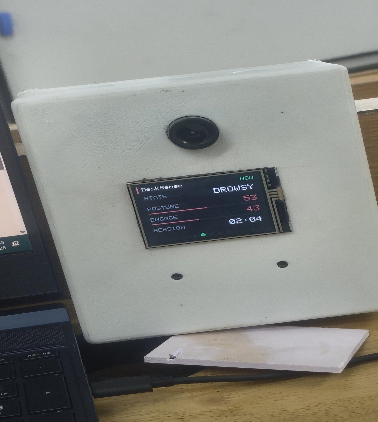
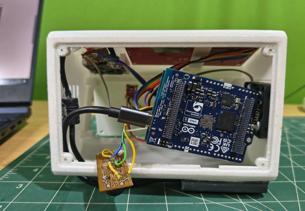
The Arduino sketch runs on the STM32U585 and communicates with the MPU via RPC. The 3.5″ ILI9488 TFT is driven over SPI — VCC on 3.3 V, MISO left disconnected (write-only mode). The display shows the current state label, posture score, engagement score, and session elapsed time, refreshing on each RPC call.
Key SPI connections: MOSI → TFT SDI (D11), CLK → TFT SCK (D13), CS (D10), DC (D8), RST (D9). LEDs connect via 220 Ω resistors to MCU GPIO (D2/D3/D4). Passive buzzer on D5. Cooling fan powered from the UNO Q 5 V rail.
Step 4: Web Dashboard
The App Lab WebUI Brick (FastAPI) serves a multi-tab dashboard on port 7000, accessible from any browser on the local network. Tabs: Home (live state + scores), Insights (session breakdown), Trends (historical charts), Focus (Pomodoro timer), Challenges, and Settings. A WebSocket stream pushes live JPEG preview frames at ~6.7 Hz. All data is stored in SQLite — 96 rows per 8-hour day at the 1-second cadence.
[DASHBOARD SCREENSHOT — Fig 4: take a screenshot of http://<board-ip>:7000]
Fig 4. DeskSense web dashboard — Home tab with live state, posture, and engagement scores.
Step 5: 3D-Printed Enclosure
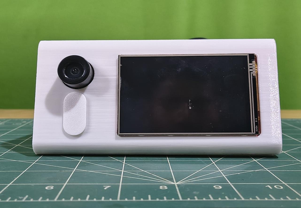
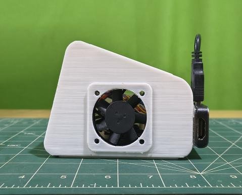
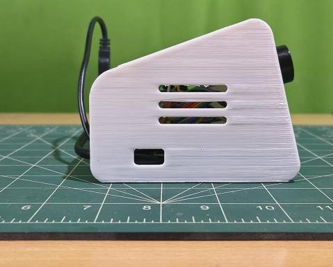
The enclosure is a wedge-style desk stand (inspired by iPhone StandBy mode) designed in OpenSCAD and printed in PLA. Dimensions: 100 mm (L) × 150 mm (W) × 80 mm front / 50 mm rear, 15° screen tilt. Front face: 86 × 56 mm TFT window, Ø21 mm camera aperture, 10 × 25 mm LED diffuser slot. A 40 × 10 mm fan exhausts through the left wall.
Step 6: Testing
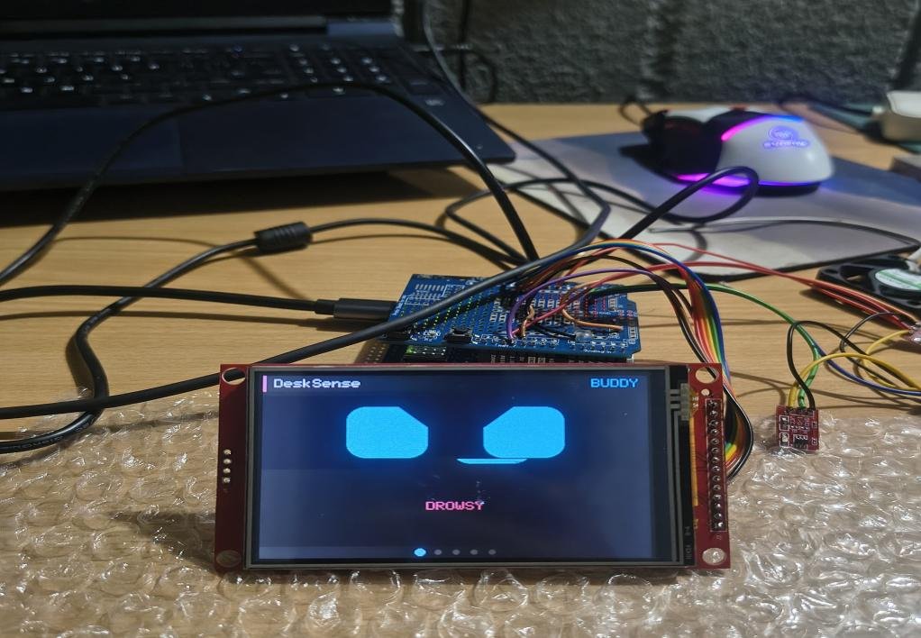
Power the UNO Q via USB-C (68 W wall adapter recommended). Connect the webcam. Open the App Lab app (DeskSense V1). Navigate to the dashboard at http://<board-ip>:7000 from any LAN browser. Sit in front of the webcam and verify: green LED lights when focused; amber LED + buzzer fires when you look away or pick up your phone; the TFT display updates state and scores in real time.
Schematics
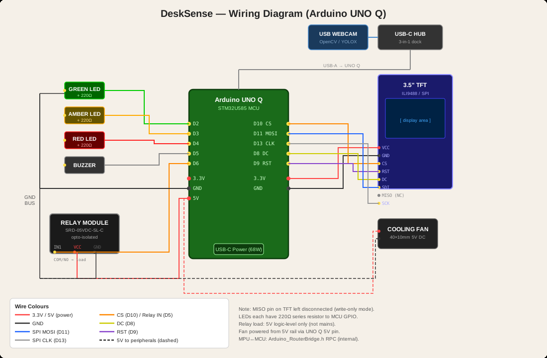
Wiring summary: UNO Q STM32 SPI → ILI9488 TFT (MOSI D11, CLK D13, CS D10, DC D8, RST D9; VCC on 3.3 V; MISO NC). MCU GPIO → Red/Green/Amber LEDs (220 Ω each, D2/D3/D4), Passive Buzzer (D5). Cooling fan → 5 V rail. USB webcam → USB-C hub → UNO Q USB-A port.
3D Enclosure Files
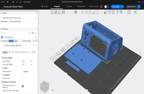
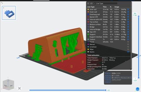
The enclosure STL files were designed in OpenSCAD and sliced using Anycubic Slicer Next (0.20 mm Standard, Anycubic PLA, Textured PEI plate). Print time: ~5h 18m, filament: 93.43 g.