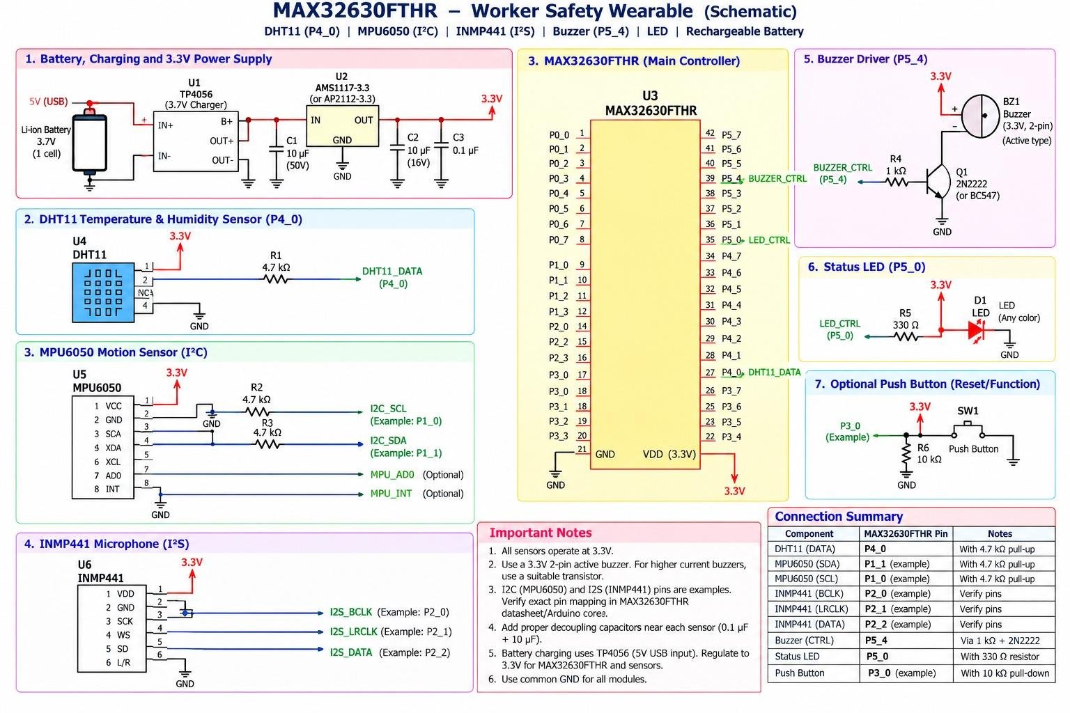
“The assistant continuously monitors the user and the workspace using its sensors and camera, tracking posture, activity, desk-time and room conditions such as temperature and lighting.” Based on these observations, the assistant automatically adjusts connected appliances, recommends posture correction, reminds users to hydrate or take breaks, and optimises the workspace for improved comfort and productivity. The system also integrates with Home Assistant and the user’s personal computer to automate productivity-related tasks.
Component List:
| ID | Name | Designator | Quantity |
|---|---|---|---|
| 1 | Microcontroller/development board | MOD1 | 1 |
| 2 | Secondary electronic module | MOD2 | 1 |
| 3 | DC–DC voltage regulator module | PWR1 | 1 |
| 4 | General-purpose prototyping PCB | PCB1, PCB2 | 2 |
| 5 | Buzzer / audible indicator | BZ1 | 1 |
| 6 | Terminal block/wiring connector | J1 | 1 |
| 7 | Tactile push button | SW1 | 1 |
| 8 | Interconnection wires/ribbon cable | W1–Wn | As Used |
| 9 | Microphone / acoustic sensor | MIC1 | [Confirm] |
| 10 | Protective earplug / wearable enclosure | ENC1 | [Confirm] |
| 11 | DC power source/battery arrangement | PS1 | [Confirm] |
Project Explanation Step By Step
Industrial machines produce identifiable sounds during normal operation. Wear, imbalance, looseness and bearing deterioration may change their acoustic signatures. Workers using conventional hearing protection may not readily hear these changes. The proposed machine-health earplug combines acoustic monitoring, embedded processing and a local alert to help workers report a possible abnormality for inspection.
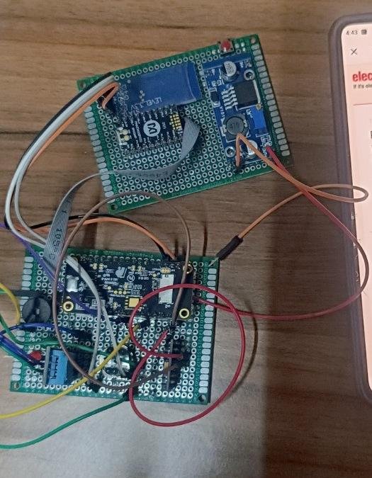
A microphone is intended to capture short machinery-audio frames. A suitable microcontroller would normalize the captured samples, extract time- and frequency-domain features, and apply a compact anomaly model or trained classifier. When the score exceeds a calibrated decision threshold for consecutive frames, an indicator would alert the worker. The threshold must be evaluated against background noise and false alerts. The photograph documents the initial wired bench electronics on two prototyping PCBs; it does not by itself confirm audio acquisition, firmware inference or wearable integration. Future work includes validation, latency measurement and safe miniaturization.
Coding Explanation and Configuration
First, identify the exact controller and verify its development environment, board support package, memory limits and audio input interface. The required driver or board libraries depend on the confirmed hardware. Configure the input sampling rate and frame length, and check the microphone output by inspecting a short captured audio waveform. The AI processing stages below describe an implementation plan; they are not presented as verified firmware from the photographed prototype.
For each audio frame, calculate a reproducible set of acoustic descriptors, for example RMS amplitude, spectral energy and selected FFT-bin or Mel-frequency features. Create training and test datasets containing separate examples of healthy-machine sound and representative anomalous conditions. Normalize features using training-set statistics, train a compact model and set an operating threshold using a held-out test set. If the controller supports on-device inference, export the model in its compatible format and integrate it into the firmware. Otherwise document which processor performs the inference.
Reference Processing Logic (Editable Pseudocode)
INITIALIZE power, audio input, processor and alert output
LOAD trained model or baseline thresholds
LOOP:
    frame = acquire_audio_frame()
    features = preprocess_and_extract_features(frame)
    anomaly_score = run_inference(features)
    IF anomaly_score >= decision_threshold for N frames:
        activate_worker_alert()
    ELSE:
        clear_worker_alert()
    record diagnostic output for testing (if enabled)
Fig 2. Editable reference pseudocode
APP Making
A dedicated Android application is not established by the current hardware photograph. This section of the sample format is retained for completeness. The initial demonstration can operate using a local buzzer, LED or vibration alert, subject to the actual wired output and firmware. An optional future mobile interface could display acoustic anomaly scores, event time, battery status and maintenance notifications over a supported wireless connection.
If an application has already been developed, replace this paragraph with the actual app-building platform, communication protocol, user-interface screenshots and tested connectivity procedure. Do not claim smartphone monitoring unless a functional app is available.
Connection Explanation
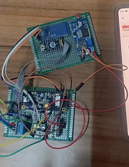
The photograph shows two prototyping PCBs connected using discrete hookup wires and a ribbon cable. The upper assembly contains an additional module and what appears to be a regulated power-supply circuit; the lower assembly contains the main development board and wired interface components. The image does not clearly show the exact component identification or pin functions. Therefore, the table below is an editable connection register to be completed from the real circuit before publication.
| Connection | From | To | Verified Pin / Voltage |
|---|---|---|---|
| Power input | [Actual supply] | DC–DC input | [Measured rating] |
| Regulated supply | PWR1 output | Controller power rail | [3.3 V / 5 V: verify] |
| Common reference | Power ground | Controller/sensor GND | [Verify continuity] |
| Acoustic interface | MIC1 output | Controller input | [ADC / I2S / PDM] |
| Alert control | Controller output | Buzzer/vibration driver | [GPIO and driver] |
| Secondary module | MOD2 | Controller interface | [UART / SPI / I2C] |
Connection procedure: (1) Confirm each module’s supply rating from its manufacturer datasheet. (2) Check power polarity and earth/ground continuity with the system unpowered. (3) Verify that the microphone interface and logic-level voltages are compatible with the processor. (4) If an indicator draws more current than a GPIO can safely source or sink, use a suitable switching driver. (5) Load a basic diagnostic firmware and separately verify audio acquisition and the alert output. (6) Only then combine the AI processing stages with the final wiring.
For a wearable product, route and secure cables, provide a protected low-voltage power source and select an alert that does not increase hazardous sound exposure. This wired board is suitable for bench development but not for direct deployment in a noisy workplace without electrical, ergonomic and hearing-protection testing.
Testing
1. Visual inspection: Inspect solder joints, supply polarity, insulation and all connectors. Power the low-voltage assembly using a current-limited source appropriate to the hardware. Record supply voltage and current before connecting other modules.
2. Sensor check: Capture a short segment of normal motor sound or use a reproducible audio replay, then check sample rate, waveform shape and saturation. If no microphone is attached, complete this step after installing the actual sensor.
3. Baseline test: Record multiple normal-operation audio windows and calculate model scores or feature statistics. Log the number of false alerts during this healthy operating condition.
4. Abnormal-sound test: Present a separate, labelled recording or a safely created abnormal machinery condition. Observe the anomaly score and warning output. Do not intentionally damage machinery or bypass factory safeguards.
5. Robustness test: Repeat at varied sound levels, background noise and sensor distances. Measure time from acoustic event to alert, sensitivity, specificity and false alarms. Enter only measured results in the submission.
Schematics