




An open-source project uses ESP32-S3 boards to build walkie-talkies that send voice messages directly, without a router or mobile network.
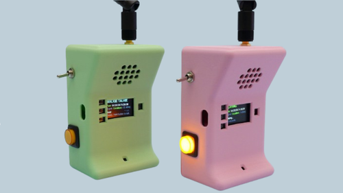
Two compact ESP32-based handsets can be built to exchange voice messages using ESP-NOW, a wireless communication protocol developed by Espressif. The project, designed by Liz Clark and published by Adafruit, combines a microcontroller development board, a digital microphone, an audio amplifier, a speaker and a push button inside a 3D-printed enclosure. Each handset records a short voice message while the button is held and transmits it to the other unit when the button is released. The receiving handset then plays the message through its speaker.
The project is documented in the Adafruit Learning System, which provides circuit diagrams, assembly instructions, firmware and printable enclosure files. It uses the Feather ESP32-S3 Reverse TFT development board, which integrates an ESP32-S3 microcontroller, a colour display and a connector for an external antenna. The design takes inspiration from handheld toy walkie-talkies popular in the early 1990s, but uses modern digital electronics to transmit recorded audio.
The communication system relies on ESP-NOW rather than a conventional Wi-Fi network. Although the ESP32-S3 contains a Wi-Fi radio, ESP-NOW allows compatible devices to exchange data directly without first connecting to a wireless router. Each handset can therefore communicate with its paired unit without requiring a mobile network or internet service. The protocol is intended for direct device-to-device communication and is also used in applications such as wireless controls, sensors and connected electronics.
Each handset uses an I2S MEMS microphone to capture voice and an I2S-compatible MAX98357A Class D amplifier to drive its speaker. I2S, short for Inter-IC Sound, is a digital interface commonly used to transfer audio data between electronic components. In this design, the microphone supplies digital audio samples to the ESP32-S3, which stores the recording before transmission. The firmware uses a sampling rate of 16kHz and 16-bit audio samples, with each recording limited to 10 seconds.
Rather than streaming audio continuously, the system follows a record-and-send approach. Holding the illuminated push button starts recording, while releasing it triggers the transmission process. The firmware divides the recording into packets for wireless transfer. The receiving unit processes the incoming data and plays the reconstructed recording through its speaker. This approach simplifies the implementation compared with a live, full-duplex voice link, although users must wait for a recording to finish transmitting before hearing it.
The handsets also provide visual feedback through their built-in displays and illuminated buttons. The screens show information such as the device’s hardware address, signal strength and communication status. The button’s light indicates activity while the units establish communication or send and receive messages. An external 2.4GHz antenna connected through an adapter is intended to improve the wireless link, although the project documentation does not specify a verified maximum communication range or battery runtime.
Building the system requires two Feather ESP32-S3 Reverse TFT boards, two I²S microphone modules, two MAX98357A amplifier breakouts, speakers, illuminated momentary push buttons, toggle switches, batteries and antenna assemblies. The project also requires wiring, soldering and 3D printing. The microphone connects to the development board’s D5, D6 and D9 pins, while the amplifier uses D10, D11 and D12. The push button connects to D13, and its illumination is controlled through A0. The power switch connects to the board’s enable pin. These connections follow Adafruit’s documented design and may need to change if builders substitute different development boards.
The firmware can be installed using a precompiled UF2 file supplied with the project guide. Builders connect the board to a computer over USB, enter its bootloader mode and copy the firmware file to the drive that appears. Alternatively, they can compile the source using the Arduino IDE and the appropriate ESP32 board package. Both handsets run the same firmware, and the project is ready to exchange messages when the two units establish communication.
The software is available under the MIT licence, with copyright attributed to Liz Clark for Adafruit Industries in 2026. The guide provides downloadable firmware and source code, allowing developers to inspect, modify and extend the implementation. The project also includes circuit diagrams and 3D-printable case files, although the licence for the enclosure designs should be checked separately before redistributing modified files. This distinction matters because the availability of source code does not automatically mean every associated design file carries the same licence.
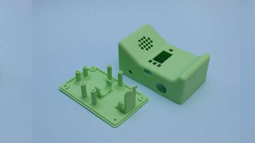
The design is intended for intermediate-level makers rather than complete beginners. Assembling the electronics requires careful wiring and soldering, particularly when fitting the microphone, amplifier and antenna connections inside the compact enclosure. Builders should also check battery compatibility, charging arrangements and electrical safety before using substitute components. Although the guide lists specific Adafruit parts, compatible alternatives may be possible, but changing the microphone, amplifier or development board can require modifications to the wiring and firmware.
For Indian students, hobbyists and engineering clubs, the project offers a practical way to learn embedded programming, digital audio processing and wireless communication. A lower-cost version could potentially use a generic ESP32-S3 development board with an I²S microphone and amplifier, although recreating the complete design would require adapting the code and display interface. Builders should compare the cost of two complete handsets, including batteries, antennas, enclosures and shipping, before choosing between the original components and alternatives.
ESP-NOW operates using Wi-Fi radio technology in the 2.4GHz band, which is subject to applicable radio-frequency regulations in India. Although certain low-power equipment can operate in designated delicensed bands, builders must ensure that their hardware, antenna configuration and transmission power comply with the relevant requirements. The project’s practical appeal is that it demonstrates direct wireless communication without relying on mobile infrastructure, while its open firmware and detailed build guide give makers a starting point for experimenting with their own embedded voice-communication devices.
For more information, click here.