


Electrical appliances such as lights, fans, air-conditioners, TVs, and water pumps are typically operated using manual switches. This system enables these appliances to be controlled over the internet using a smartphone. It combines an ESP-01 Wi-Fi module, the Switchsys MQTT broker (free public version), and the IoT MQTT panel app. The Switchsys MQTT broker implements the MQTT publish/subscribe communication model, enabling communication between the ESP-01 module and the user interface.
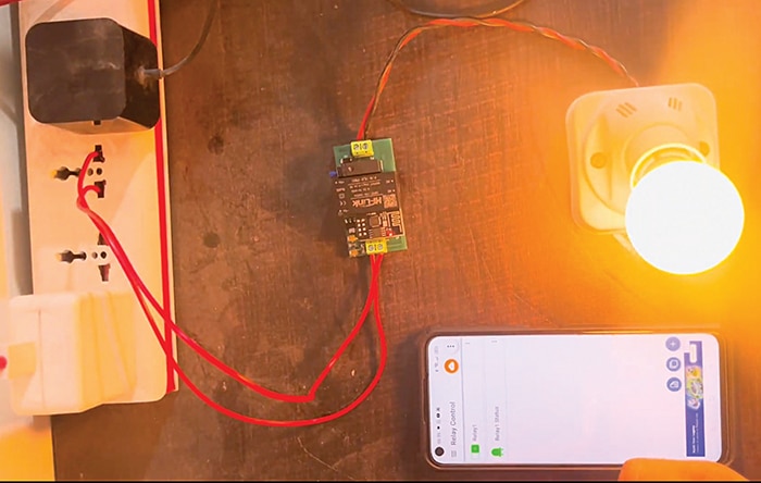
The IoT MQTT panel mobile application allows users to send on/off commands and monitor device status in real time from any location with internet access. Commands sent through the app are routed via the MQTT broker to the ESP-01, which processes the subscribed topic and drives the relay accordingly. This enables remote control of connected appliances from virtually anywhere. Fig. 1 shows the author’s prototype, while Table 1 lists the components required to build the system.
| Table 1 Bill of Materials | |
| Components | Quantity |
| ESP-01 Wi-Fi module (ESP8266 SoC based) | 1 |
| 8-pin ESP-01 connector | 1 |
| ESP-01 USB programmer adaptor | 1 |
| Relay driver IC ULN2003A (U2) | 1 |
| Relay HF46F/5-HS1 | 1 |
| Diode 1N4007 (M7) | 1 |
| HLK-PM01 230V AC to 5V DC converter | 1 |
| 10kΩ resistor (R1-R3) | 3 |
| 2-pin 5.08mm pitch plug-in screw terminal block connector | 2 |
| AMS1117-3.3 voltage regulator – U3 (5V DC to 3.3V DC) | 1 |
| 100nF ceramic capacitor (C2, C3) | 2 |
| 22µF tantalum capacitor (C1, C4) | 2 |
The system uses an ESP-01 Wi-Fi module, a relay module, the Switchsys MQTT broker, and the IoT MQTT Panel app. It becomes operational when powered on. The ESP-01 connects to the Wi-Fi network and communicates with the MQTT broker. The user sends on/off commands through the mobile app, which the ESP-01 receives via the broker. Based on the received command, the ESP-01 activates or deactivates the relay to switch the connected bulb on or off.

System design
In the IoT MQTT Panel app dashboard, there is a single switch to control the relay and an LED indicator to display the relay status.
When Relay1 switch is turned on, the app publishes payload 1 to the topic switchsys/relay1 and sends it to the ESP-01 over the internet via the Switchsys MQTT broker (broker URL: mqtt.switchsys.in, port: 1883). Since the ESP-01 is subscribed to the same topic (switchsys/relay1), it receives payload 1 and sets GPIO0 HIGH, thereby energising the relay.

After energising the relay, the ESP-01 publishes the relay status to the topic switchsys/relay1/status. This status message is then sent back to the IoT MQTT Panel app through the MQTT broker. In the app, the LED indicator is subscribed to the topic switchsys/relay1/status. Therefore, when payload 1 is received, the LED indicator turns green, indicating that the relay is on.
Similarly, when the relay switch is turned off in the IoT MQTT Panel app, payload 0 is transmitted to the ESP-01 via the topic switchsys/relay1. The ESP-01 then sets GPIO0 LOW, de-energising the relay, and publishes the updated relay status with payload 0 to the topic switchsys/relay1/status. Upon receiving this payload, the LED indicator changes to grey, indicating that the relay is off. Table 2 shows the MQTT topics and payload details used in the project.
| Table 2 MQTT publish/subscribe details | |||||
| Component | Type | Action | Topic | Payload | Function |
| IoT MQTT app | Publish | Relay switch on | Switchsys/relay1 | 1 | Energises relay |
| IoT MQTT app | Publish | Relay switch off | Switchsys/relay1 | 0 | De-energises relay |
| IoT MQTT app | Subscribe | — | Switchsys/relay1/status | 1 | LED indicator turns green |
| IoT MQTT app | Subscribe | — | Switchsys/relay1/status | 0 | LED indicator turns grey |
| ESP-01 | Subscribe | — | Switchsys/relay1 | 1 | Turns relay on |
| ESP-01 | Subscribe | — | Switchsys/relay1 | 0 | Turns relay off |
| ESP-01 | Publish | Relay energised | Switchsys/relay1/status | 1 | Sends on status to app |
| ESP-01 | Publish | Relay de-energised | Switchsys/relay1/status | 0 | Sends off status to app |
Circuit diagram
Fig. 2 shows the circuit diagram of the system. It is built around the ESP-01 Wi-Fi module, the AMS1117-3.3 voltage regulator (5V DC to 3.3V DC), the ULN2003A relay driver IC, the HLK-PM01 230V AC to 5V DC converter module, the HF46F/5-HS1 relay, the 1N4007 diode, and a few other components.
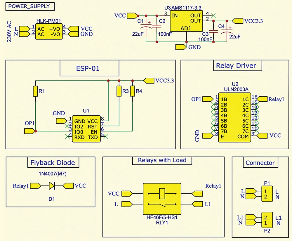
EFY note. This system uses the ESP-01 module, and the GPIO pins are selected accordingly. Other ESP8266-based boards, such as NodeMCU and WeMos D1 Mini, can also be used with this system. In that case, only the ESP-01 module needs to be replaced, and the GPIO pin connections should be modified accordingly.
Software

