


Traditional GPS-based systems have limitations, especially indoors or in areas where signals are too weak or difficult to get due to obstructions. Can you add location tracking without GPS?
Yes, you can! This project demonstrates how you can add location tracking, without GPS, to the project for a smartwatch-like HID with keyboard and touch-pad, which was published in March issue.
This is a novel approach to location tracking using Wi-Fi SSID signals, magnetic compass data, and the Indusboard, which is a compact IoT device with Wi-Fi capabilities and a magnetic compass sensor. By leveraging Wi-Fi signals and compass data, real-time location tracking can be achieved even in challenging environments.
SSID stands for service set identifier, an important identifier for wireless networks that is assigned to a Wi-Fi network during router setup.
POC Video Tutorial In English:
The SSID-based location tracking system can be applied in various scenarios such as indoor navigation in buildings where GPS signals are weak or unavailable, asset tracking in warehouses or manufacturing facilities, monitoring and tracking personnel movement in large venues or events, and location-based advertising and marketing campaigns.
| Bill of Materials | ||
| Components | Description | Quantity |
| Indusboard or ESP32 | Development board | 1 |
| USB Type C | Adaptor | 1 |
| GC9A01 driver (MOD1) | Round touch display | 1 |
| CST816S touch sensor (CN1) | Touch sensor | 1 |
Note: The Indusboard has a built-in 3D magnetic compass sensor for direction sensing. While using ESP32, an external compass sensor will need to be added.
Here, the Indusboard (or an ESP32) is used to scan and connect to networks, extracting location data based on the network. It also utilises a magnetic compass to determine direction. Using the GC9A01 round display, the device shows the location data and connection states to the user wearing it.
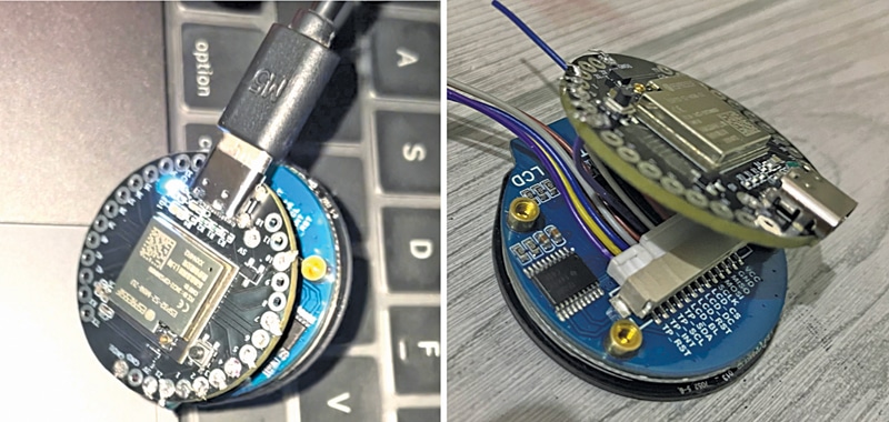
The author’s prototype is shown in Fig. 1. The components required for the project are listed in Bill of Materials table.
Code to Add Location Tracking
For coding, install the Arduino_GFX library, which helps drive the display. This library can be installed using the library manager found in the left bar of the new Arduino IDE.
Next, set the SPI display pins. On the board, any free pins can be configured; this is why the Indusboard has flexible software SPI capabilities. We have used pins 21, 1, 2, and 3 of the Indusboard for SPI, connecting them to the MOSI, SCK, CS, and D/C pins of the GC9A01 driver (MOD1), respectively.
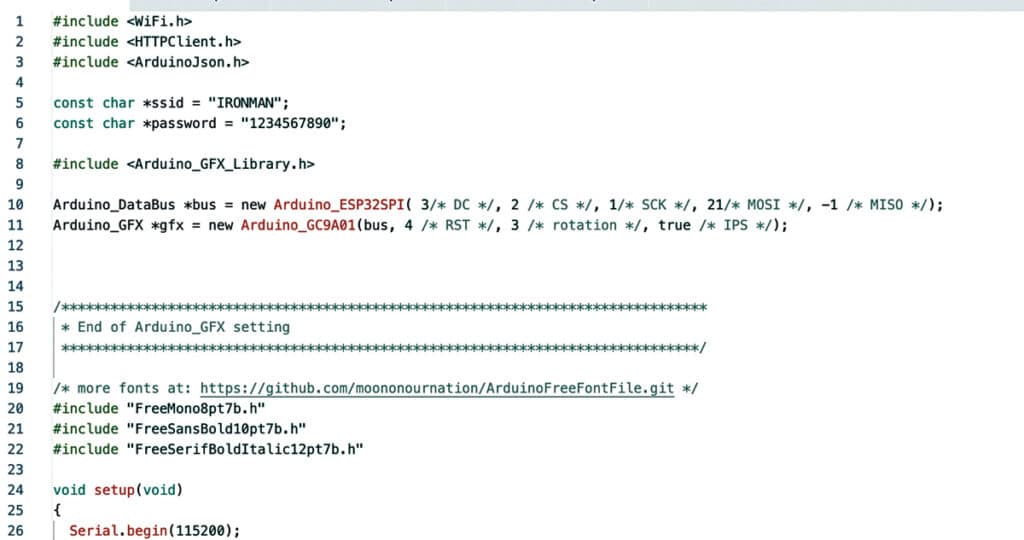
Fig. 2 shows a snippet of the source code.
Circuit and working
Fig. 3 shows the circuit diagram for wearable location tracking using SSID. It is built around the Indusboard coin type, round touch display GC9A01 driver (MOD1), and touch sensor CST816 (CN1). A USB Type C is used to connect the Indusboard to a laptop or desktop.
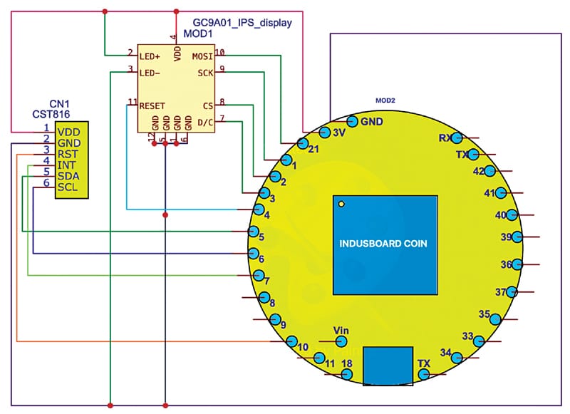
The connections are straightforward. Connect pins 21, 1, 2, 3, and 4 of the Indusboard to the MOSI, SCK, CS, D/C, and RESET pins of the GC9A01 driver (MOD1), respectively. Similarly, connect pins 5, 6, 7, and 9 of the Indusboard to the SDA, SCL, INT, and RESET pins of the CST816 (CN1), respectively.
Construction and testing
First, configure the Wi-Fi network to connect with and extract the location, time zone, and other data. After completing the configuration in the source code, upload the source code by selecting the Indusboard or ESP32S2 and the COM port.
Next, solder the components as shown in Fig. 4. After proper assembly, your device is ready for testing.
Testing of the SSID-based location tracking system involves the following steps:
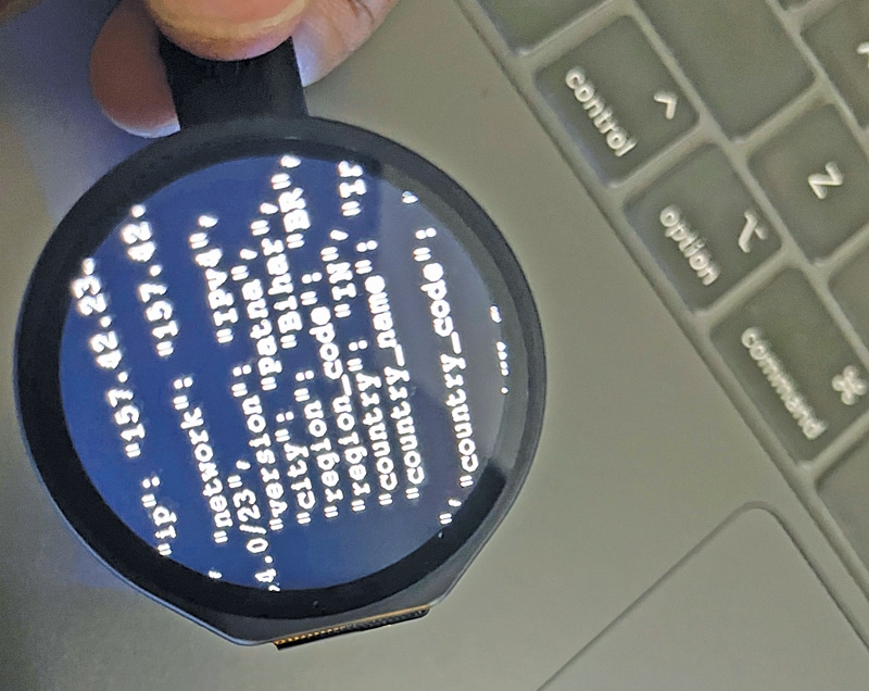
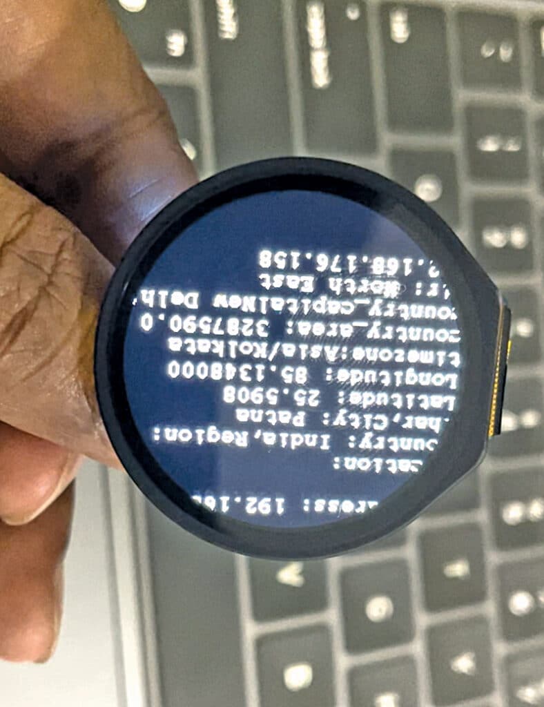
Power the device using the USB-C or 3.3V battery connected to the 3V and GND pins on the board. Wait a few seconds; it will display a “connecting” message. After a successful connection, it will display data such as country, population, time zone, country code, latitude, longitude, city, state, pin code, network name, IP address, and much more. The final data displayed on the device is shown in Fig. 5.
Ashwini Kumar Sinha, an IoT and AI enthusiast, is a tech journalist at EFY