


Back in earlier days, when the word Internet of Things (IoT) was not a sound bite, developers of this field used various Wi-Fi shields to enable the Wi-Fi feature in their development boards. Following this, in 2014, the low-cost Wi-Fi enabled chip ESP-01 caught everyone’s attention.

Espressif developed Wi-Fi enabled microchip – ESP8266 proved to be a boon in the IoT field. This caused the arrival of various other ESPs and Open Source Development boards thereby allowing even a novice to make Wi-Fi featuring applications.

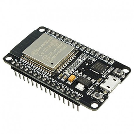
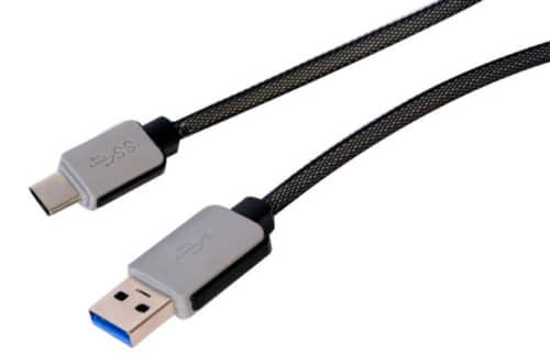
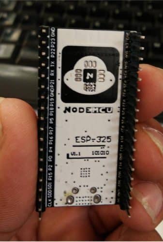
In our project, we are going to use ESP-32 NodeMCU. ESP-32 is a series of low-cost and low-power system-on-chip (SoC) microcontrollers with integrated Wi-Fi and dual-mode Bluetooth. The microcontroller is cheap with low-power consumption and a great number of pins. Evidently, with its varied features, IoT becomes easier when it comes to ESP-32. Our project is automation using ESP-32 over a local web server. On a local web server, we do not require Internet and handling everything over Wi-Fi is possible. Here, we will be handling the Input-Output pins and switching relays on a web page of the local server. We can connect our home appliances with the Relay Module that will be driven by ESP-32. To get started, we need the following material. 1. ESP-32 NodeMCU – Please check the datasheet from the Internet, if you have a different manufacturer version. 2. USB type C cable – which is needed to program the ESP 32 from our Laptop or PC. Most of the android phones use this type of cable only.
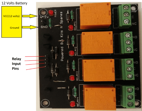
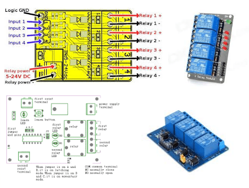
3. Relay Module – Relay is a switching Module. In a relay, we can control switching AC or DC appliances digitally by providing input to relay input pins. Here we have used a 4-channel relay operating on a 12 Volts battery.
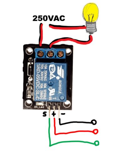
To connect your AC appliance, use the following connection.
4. Connecting Wires – To connect ESP 32 Pins from the Relay Module Pins. 5. Power Supply for ESP-32(5 Volts or can be powered from Laptop or PC directly via the USB Type C cable)
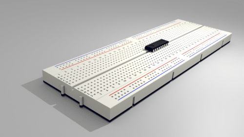
and Relay (depending on the relay module, we have used 12 Volts supported one. You can use 5 volts one also depending on your load) 6. Breadboard – to have a platform for the prototype.
Steps for the software setup:
Ignore this step if you already have the setup of ESP boards in Arduino IDE
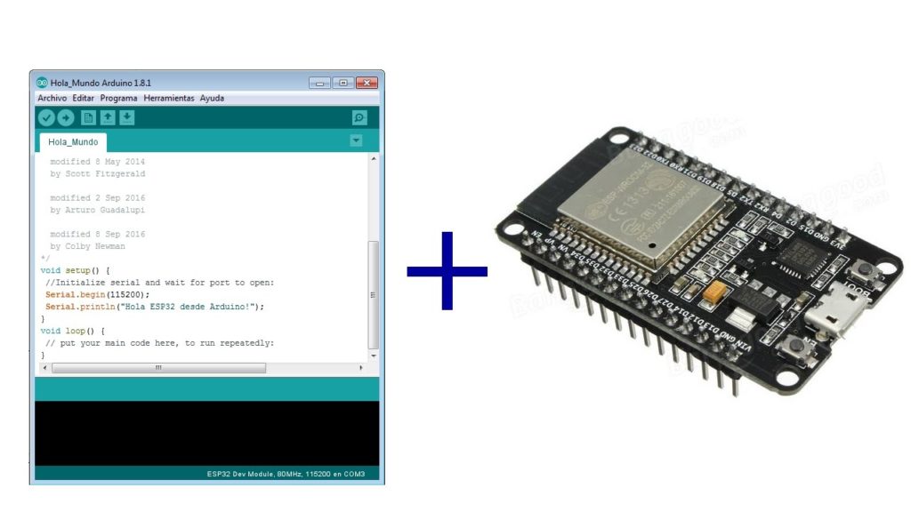
Here to code the ESP32 we need an Integrated Development Environment and we will use Arduino IDE software. Arduino IDE is a cross-platform application. It is written in Java and coded in C/C++ with some special rules. To download the latest Arduino IDE from here. Arduino IDE does not contain support of ESP32 family so to install the ESP-32 Board in Arduino IDE, you can refer here.
Connection and Wiring
These are the Relay-ESP32 connection.
| ESP-32 | Relay Module (connect your AC appliances to relays as well) |
| GPIO 4 | Relay Pin 1 |
| GPIO 16 | Relay Pin 2 |
| GPIO 17 | Relay Pin 3 |
| GPIO 5 | Relay Pin 4 |
| Table 1: Connections of Relay Module to ESP-32 | |
Do remember to check to check with your ESP 32s datasheet. The GPIO (General Purpose Input Output) Pin numbers are mentioned in the back of it.
Additionally, Esp-32 will be powered by 5 Volts supply (Current not more than 500mA) or directly plug in within the help of a USB or Power Bank. The relay module will also be powered depending on its need. Some are 12 Volts and some 5 Volts(current<=1A). Note: All grounds must be common.
The Code
- Download the Code from the link below and Open it in Arduino IDE.
- Let’s understand the code;
- Before uploading you need to make some changes in the code.
- Edit your Wifi name and Password here within the double quotes.
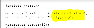
In the code, #include <WiFi.h>, helps the Arduino IDE to run the functions of ESP 32 in it. This library contains all the Wifi.xxxx functions used in the code. These 3 lines can be removed if your ESP board does not have any Brownout error.
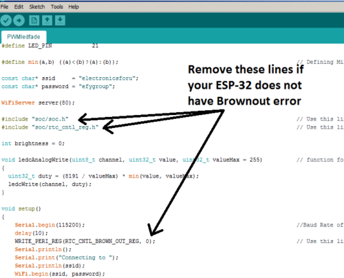
In the void setup(){}, we perform all the setup needed for the main program to run like Baud rate in Serial.begin(), Wifi initialization, pin mode setup and start the server from Server.begin(). In void loop(), we have our main program. Our aim is first to create a Web Page on the server and then attach it with various buttons. To create this web page we need HTML code embedded in it like this. client.println(“HTTP/1.1 200 OK”); client.println(“Content-type:text/html”); client.println(); // the content of the HTTP response follows the header client.print(“<a href=\”/A\”>Light 1 ON </a><br>”); client.print(“<a href=\”/B\”>Light 1 OFF</a><br>”); client.print(“<a href=\”/C\”>Light 2 ON</a><br>”); client.print(“<a href=\”/D\”>Light 2 OFF</a><br>”); client.print(“<a href=\”/E\”>Light 3 ON</a><br>”); client.print(“<a href=\”/F\”>Light 3 OFF</a><br>”); client.print(“<a href=\”/G\”>Light 4 ON</a><br>”); client.print(“<a href=\”/H\”>Light 4 OFF</a><br>”); client.println(); // The HTTP response ends with another blank line break; // break out of the while loop Whenever these buttons are pressed, a function of HIGH or LOW is performed on the Output pins(GPIO pins) of ESP32 by detecting the last character from the If loop. if (currentLine.endsWith(“GET /A”)) { digitalWrite(4, HIGH); //GET /A turns the Light 1 ON } if (currentLine.endsWith(“GET /B”)) { digitalWrite(4, LOW); //GET /B turns the Light 1 OFF } if (currentLine.endsWith(“GET /C”)) { digitalWrite(16, HIGH); // GET /A turns the Light 2 ON } if (currentLine.endsWith(“GET /D”)) { digitalWrite(16, LOW); // GET /B turns the Light 2 OFF } if (currentLine.endsWith(“GET /E”)) { digitalWrite(17, HIGH); // GET /A turns the Light 3 ON } if (currentLine.endsWith(“GET /F”)) { digitalWrite(17, LOW); // GET /B turns the Light 3 OFF } if (currentLine.endsWith(“GET /G”)) { digitalWrite(5, HIGH); // GET /A turns the Light 4 ON } if (currentLine.endsWith(“GET /H”)) { digitalWrite(5, LOW); // GET /B turns the Light 4 OFF } These pins attached to the Relay Input pins can switch the appliances. Now, Save the code and Connect ESP-32 with your PC or Laptop using micro USB type B cable.
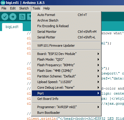
- Go to Tools>Boards Manager>ESP32 Dev Module.
- Go to Tools>Upload Speed>115200
- Select your COM Port.
- Upload the Code and Power up everything.
Connecting the web server
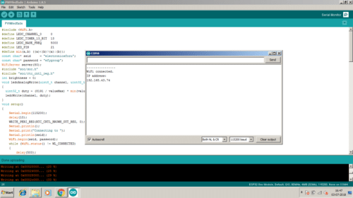
After the uploading is done, Open Tools>Serial Monitor. The ESP-32 will try to connect with your Wifi and display its IP address.
- Make sure that your Wifi/Router to be connected is already open.
- Now, hit this IP address in the browser of a device connected to same Wifi
- Url: http://192.168.xx.xx (your IP displayed in Arduino Serial Monitor)
- Now You will be able to see the HTML webpage mentioned in the code.
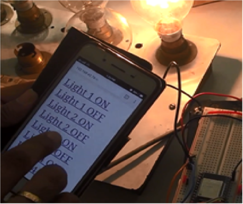
Now, you can turn On and OFF your desired AC appliance by pressing the buttons on the HTML page.
Wow
Nice videos………. i would like to share it …..
As a good learner one should follow this article and explore more .
Nice work!!
Thank you for your feedback.
I really like the IOT related project explain in detail …
thank you !!!
plz put also new things about it…
Thank you so much for this great Project. I just want to know one more thing, Can we use any apps
like “Blynk” instead of creating a HTML Web Page on the server??? if it’s possible then please reply with how can we do….
how to create that html page ???
pls tell
code not importing in ide